car cleaning method
An automobile and solenoid valve technology, applied in vehicle maintenance, vehicle maintenance/repair, transportation and packaging, etc., can solve the problems of unfavorable auto repair shop cost control, spending more time, single function, etc., to achieve convenient operation and use. , the effect of simple operation
- Summary
- Abstract
- Description
- Claims
- Application Information
AI Technical Summary
Problems solved by technology
Method used
Image

Examples
Embodiment 1
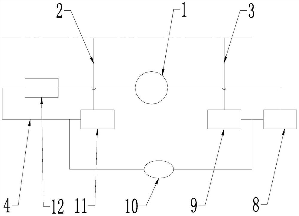
[0034] Such as figure 1 As shown, the present embodiment is a car cleaning method, including car maintenance equipment, the car maintenance equipment includes a closed shell, figure 1 The double dotted line in indicates the shell of the device. Inside the housing are arranged a first barrel 1 , a drive pump 10 , an output line 2 and a return line 3 . A pipeline is connected between the first barrel body 1 and the inlet of the driving pump 10, and a first electromagnetic valve 8 is installed on the pipeline. One end of the return pipeline 3 is connected to the first electromagnetic valve through a three-way joint. On the pipeline between the valve 8 and the inlet of the drive pump 10 , a second solenoid valve 9 is installed on the return pipeline 3 . The outlet of the driving pump 10 is connected to one end of the output pipeline 2, and a third electromagnetic valve 11 is installed on the output pipeline 2; the recovery pipeline 4 is also branched on the output pipeline 2 thr...
Embodiment 2
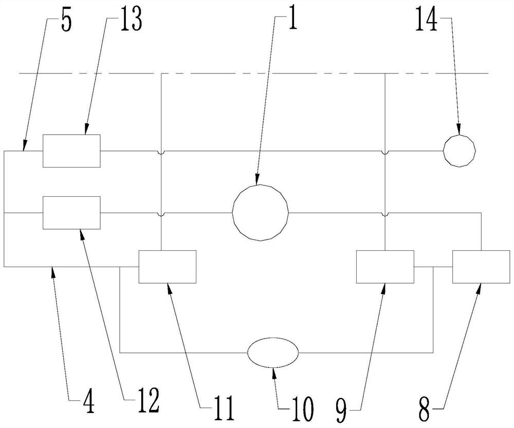
[0050] Such as figure 2 As shown, this embodiment also includes a waste liquid pipeline 5 and a second barrel 14 branched to the recovery pipeline 4, and the waste liquid pipeline 5 and the second barrel 14 are also located in the housing. One end of the waste liquid pipeline 5 is branched to the inlet side of the fourth electromagnetic valve 12 through a three-way joint, and the other end of the waste liquid pipeline 5 is connected to the second barrel 14. On the waste liquid pipeline 5 A fifth solenoid valve 13 is installed. When the service life of the cleaning liquid is short or it is necessary to store the cleaning waste liquid separately from the cleaning liquid in the first barrel 1 or to recycle the waste liquid at the part of the car to be cleaned, the waste liquid pipeline 5 can be used to remove the waste liquid. The liquid is recovered in the second bucket body 14. Other structures of this embodiment are the same as those of Embodiment 1, and will not be repeate...
Embodiment 3
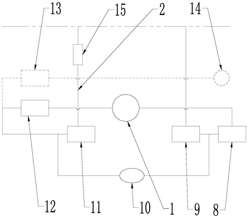
[0067] Such as image 3 As shown, a heating device 15 is installed on the output pipeline 2 , and the heating device 15 is located on the outlet side of the third solenoid valve 11 . The specific method of the heating device 15 is not limited, it can be a box structure with electric heating rods, or the output pipeline 2 disks are arranged in the electric heating disk, and those skilled in the art can choose according to various factors such as cost and layout space. Appropriate way is enough. This embodiment preferably adopts a box structure with a built-in electric heating rod. In order to further improve the cleaning effect, a temperature monitoring device is installed on the heating device 15 or the output pipeline 2, so as to monitor the temperature of the cleaning liquid before and after heating for easy control. Other structures of this embodiment are the same as those of Embodiment 1 or Embodiment 2, and will not be repeated here.
[0068] If the present embodiment ...
PUM
 Abstract
Description
Claims
Application Information
 - R&D
- Intellectual Property
- Life Sciences
- Materials
- Tech Scout
- Unparalleled Data Quality
- Higher Quality Content
- 60% Fewer Hallucinations
Browse by: Latest US Patents, China's latest patents, Technical Efficacy Thesaurus, Application Domain, Technology Topic, Popular Technical Reports.
© 2025 PatSnap. All rights reserved.Legal|Privacy policy|Modern Slavery Act Transparency Statement|Sitemap|About US| Contact US: help@patsnap.com