
Printing head

A technology of printer head and body, applied in coating devices, additive processing, etc., can solve the problems of limited printing size and inability to meet the needs of large parts production, and achieve increased printing scale, compact structure, and equipment structure. simple effect

Inactive Publication Date: 2019-01-11
帅向义
View PDF0 Cites 2 Cited by
  • Summary
  • Abstract
  • Description
  • Claims
  • Application Information

AI Technical Summary

Problems solved by technology

[0002] With the development of society, there are more and more types of printer heads, and the range of applications is becoming wider and wider. Among them, 3D printing technology has higher printing accuracy and higher complexity. It does not need the characteristics of the mold during the printing process, so It has broad development prospects, but it is also limited by the frame of the printer during the printing process, the size of the print is limited, and it cannot meet the production needs of large parts, so a device is needed to solve such problems

Method used


Image

  • Printing head
  • Printing head
  • Printing head

Examples


Embodiment Construction

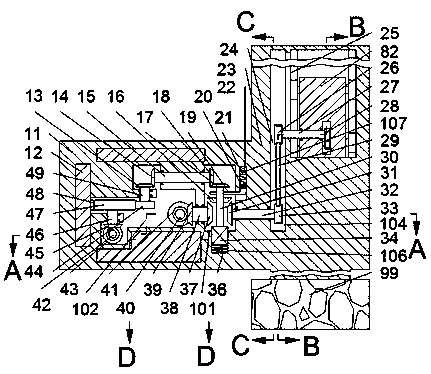
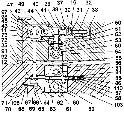
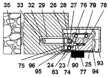
[0020] Such as Figure 1-Figure 5 As shown, a printer head of the present invention includes an upper body 11 and a lower body 12 located below the upper body 11, a first cavity 101 is arranged in the upper body 11, and the first A first rotating shaft 30 extending forward and backward is rotated in the cavity 101, and the rear end of the first rotating shaft 30 is power-connected with a motor 34 arranged in the front end wall of the first cavity 101. The outer surface of a rotating shaft 30 is fixedly provided with a first bevel gear 16, and the left side of the first cavity 101 is provided with a second cavity 102, and the rotation between the second cavity 102 and the first cavity 101 A second rotating shaft 38 extending left and right is provided, and the right end of the second rotating shaft 38 in the first cavity 101 is fixedly provided with a second bevel gear 37 disengaged from the first bevel gear 16 , The left end of the second rotation shaft 38 in the second cavit...


PUM


Abstract

The invention discloses a printing head, comprising an upper printer body and a lower printer body located below the upper printer body, wherein the upper printer body is provided with a first cavity;a first rotating shaft extending front and back is rotatably arranged in the first cavity; the tail end of the rear side of the first rotating shaft is in power connection with a motor arranged in the end wall of the front side of the first cavity; a first bevel gear is fixedly arranged on the outer surface of the first rotating shaft; and a second cavity is arranged at the left side of the firstcavity. The printing head of the invention is simple in structure and convenient to maintain and repair; at the same time, electric energy is utilized to drive a mechanical structure so as to automatically lift the printing head to print a 3D model; a wheeled walking structure is employed so as to increase the printing scale of the printing head, and the printing head is compact in structure andreduced in occupied land area; and through the use of a balance beam mechanism, the stability of the printing head during working is improved, and the automation degree and practicality of the printing head are enhanced.

Description

technical field [0001] The invention relates to the field of rapid prototyping, in particular to a printer head. Background technique [0002] With the development of society, there are more and more types of printer heads, and the range of applications is becoming wider and wider. Among them, 3D printing technology has higher printing accuracy and higher complexity. It does not need the characteristics of the mold during the printing process, so It has broad development prospects, but it is also limited by the frame of the printer during the printing process, and the size of the print is limited, which cannot meet the production needs of large parts, so a device is needed to solve such problems. Contents of the invention [0003] The technical problem to be solved by the present invention is to provide a printer head, which can solve the above-mentioned problems in the prior art. [0004] The present invention is achieved through the following technical solutions: a prin...

Claims


Application Information

Patent Timeline
Patent Type & Authority Applications(China)
IPC IPC(8): B29C64/209B29C64/20B33Y30/00
CPCB29C64/209B29C64/20B33Y30/00
Inventor 帅向义
Owner 帅向义
Learn More