Eureka AIR delivers breakthrough ideas for toughest innovation challenges, trusted by R&D personnel around the world.

Main pin shaft drilling clamping device for spinning machine

A clamping device and kingpin technology, which is used in positioning devices, clamping, metal processing machine parts, etc., can solve the problems of scrap parts, offset of kingpins, etc. Guaranteed effect of accuracy

Inactive Publication Date: 2019-01-11
盐城瑞嘉纺织制品有限公司
View PDF0 Cites 0 Cited by
  • Summary
  • Abstract
  • Description
  • Claims
  • Application Information

AI Technical Summary

Problems solved by technology

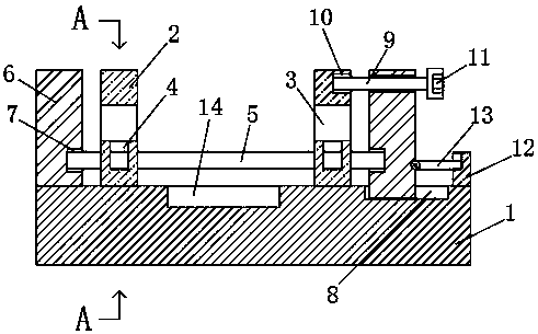
[0003] The purpose of the present invention is to solve the problem in the prior art that using clips to clamp the cylindrical kingpin shaft will easily cause the position of the kingpin shaft to shift and cause the parts to be scrapped, and the proposed spinning machine uses the kingpin shaft to drill and clamp device

Method used


Image

  • Main pin shaft drilling clamping device for spinning machine
  • Main pin shaft drilling clamping device for spinning machine

Examples


Embodiment Construction

[0017] The following will clearly and completely describe the technical solutions in the embodiments of the present invention with reference to the accompanying drawings in the embodiments of the present invention. Obviously, the described embodiments are only some, not all, embodiments of the present invention.

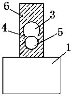
[0018] refer to Figure 1-2 , the kingpin shaft drilling and clamping device for the spinning machine, including a base 1, the upper side wall of the base 1 is provided with a collection groove 14, the collection groove 14 is located between the two mounting seats 2, and the kingpin shaft 5 is punched When the hole is drilled, the metal waste produced falls into the collection tank 14 for centralized collection. The side of the base 1 near the chute 8 is fixedly connected with a fixed block 12. The fixed base 6 which is slidingly connected is connected with the clamping rod 13 matched with the slot through the rotating shaft, and is snapped into the slot through the ...


PUM


Abstract

The invention discloses a main pin shaft drilling clamping device for a spinning machine. The main pin shaft drilling clamping device comprises a base, wherein two mounting seats are arranged on the side wall of the upper end of the base, the side wall of each two mounting seat is provided with a through hole, and a clamping hole is formed in the side wall of the lower end of each mounting seat; each through hole communicates with the corresponding clamping hole, each clamping hole is located above the corresponding through hole, and a main pin shaft is arranged between the two clamping holes;the main pin shaft abuts against the side walls of the clamping holes, and two fixing seats are arranged on the side wall of the upper end of the base, and a groove is formed in the side wall, closeto the corresponding mounting seat, of each fixing seat; the main pin shaft penetrates through the clamping holes and extends into the grooves, and the side wall of each groove abuts against the mainpin shaft; and a sliding groove is formed in the side wall of the upper end of the base, and one fixing base is connected with the sliding groove in a sliding manner. According to the main pin shaft drilling clamping device, the clamping holes and the grooves are tightly abutted against the main pin shaft, and then fixing bolts are used for fixing the positions of the fixing seats, so that the main pin shaft is firmly fixed, punching can be accurately and rapidly carried out, and the production efficiency is improved.

Description

technical field [0001] The invention relates to a kingpin shaft drilling and clamping device for a spinning machine. Background technique [0002] Drilling is required during the processing of the kingpin shaft for wire machines, so as to facilitate installation. Since the kingpin shaft is columnar, the general clamping device is not ideal for clamping, and it often deviates when drilling. Parts are scrapped, the yield is low, and the production cost increases. Therefore, we propose a kingpin shaft drilling and clamping device for spinning machines to solve the above problems. Contents of the invention [0003] The purpose of the present invention is to solve the problem in the prior art that using clips to clamp the cylindrical kingpin shaft will easily cause the position of the kingpin shaft to shift and cause the parts to be scrapped, and the proposed spinning machine uses the kingpin shaft to drill and clamp device. [0004] In order to achieve the above object, the ...

Claims


Application Information

Patent Timeline
IPC IPC(8): B23Q3/06
CPCB23Q3/062
Inventor 倪伟
Owner 盐城瑞嘉纺织制品有限公司
Why Eureka
Eureka Blog
Learn More