
Automatic injection pen

An automatic injection and drive sleeve technology, applied in the direction of automatic injectors, syringes, hypodermic injection devices, etc., can solve the problems of complex internal structure, influence on popularization and application, and high production cost, and achieve the effect of reducing production cost and simplifying the internal structure

Pending Publication Date: 2019-01-11
JIAXING SUMMED MEDTECH CO LTD
View PDF1 Cites 3 Cited by
  • Summary
  • Abstract
  • Description
  • Claims
  • Application Information

AI Technical Summary

Problems solved by technology

[0003] Among the existing automatic injection pens, for example, the patent application document CN201611226505 discloses a card-type automatic injection pen, which requires the cooperation of a button mechanism, a card-type needle mechanism, and a firing mechanism to realize the release and injection of the needle. , its internal structure is relatively complex and its production cost is high, which affects its promotion and application, and increases the burden of users' purchase and use

Method used


Image

  • Automatic injection pen
  • Automatic injection pen
  • Automatic injection pen

Examples


Embodiment Construction

[0048] The idea, specific structure and technical effects of the present invention will be further described below in conjunction with the accompanying drawings, so as to fully understand the purpose, features and effects of the present invention.

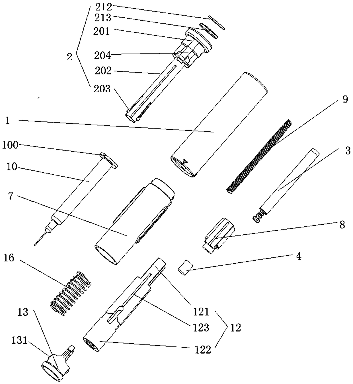
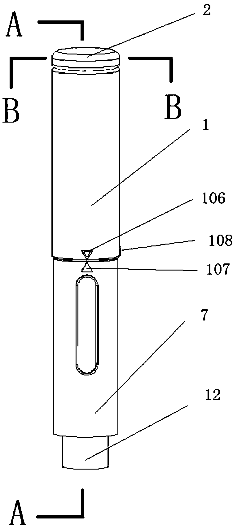
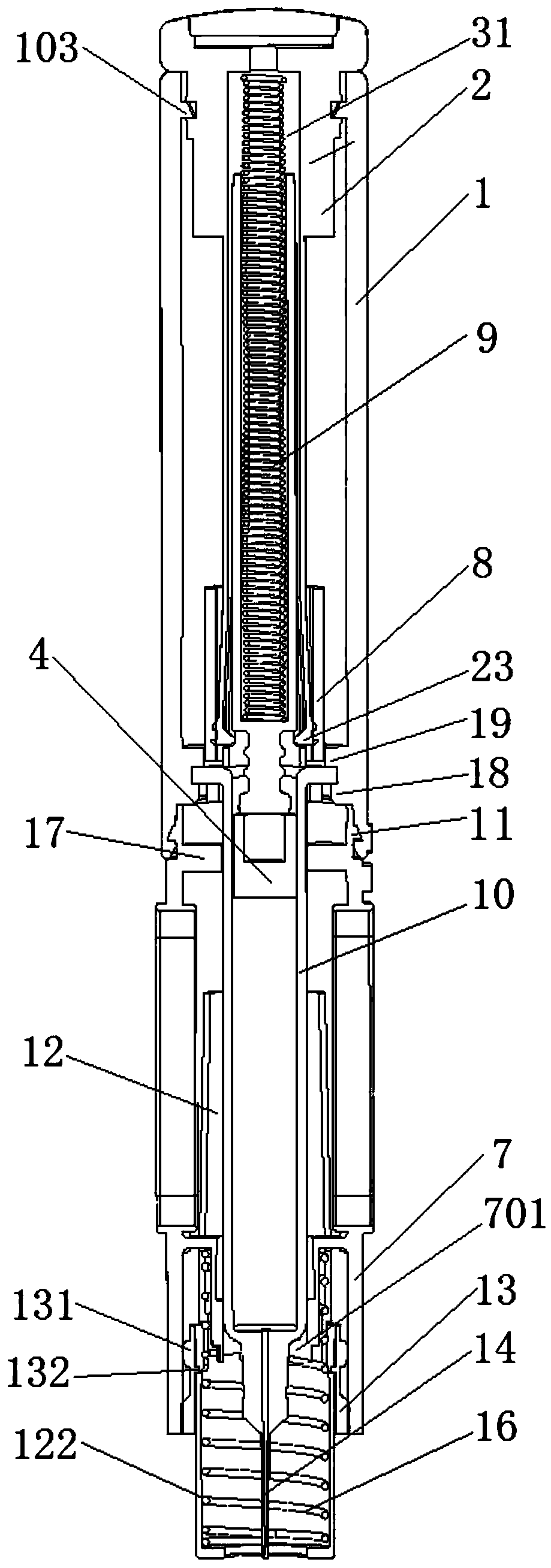
[0049] Such as Figure 1 to Figure 13 As shown, the first embodiment of the present invention provides an automatic injection pen, which includes: an upper housing 1, a lower housing 7, a syringe 10, a piston rod 3 for squeezing the inner space of the syringe 10, a sleeve A drive sleeve 2, a trigger ferrule 8, a trigger sleeve 12, etc. are provided with the piston rod 3;

[0050] Wherein, the trigger ferrule 8 is sheathed on the driving sleeve 2 , and is slidably connected with the upper housing 1 along the axial direction of the upper housing 1 , so as to clamp and connect the piston rod 3 .

[0051] The trigger sleeve 12 is arranged inside the lower housing 7 and is slidably connected with it along the axial direction of the low...


PUM


Abstract

The invention provides an automatic injection pen, including an upper housing, a lower housing, a syringe, a piston rod for squeezing an inner space of the syringe, a drive sleeve sleeved with the piston rod, and a trigger sleeve sleeved on the drive sleeve and slidably connected with the upper housing along an axial direction of the upper housing for clamping the piston rod. The triggering sleevearranged inside the lower housing and slidably connected with the lower housing along the axial direction thereof, for pushing the triggering sleeve to move along the axial direction of the upper housing so that the triggering sleeve and the piston rod are disengaged from the clamping connection, and pushing the piston rod to squeeze the syringe barrel through the driving sleeve; the upper housing and the lower housing are pivotally connected in the circumferential direction thereof so that the trigger sleeve can be pushed by the trigger sleeve when the trigger sleeve is in the open positionby relative rotating between the upper housing and the lower housing. Compared with the prior art, the present application can simplify the internal structure of the automatic injection pen and reducethe production cost.

Description

technical field [0001] The invention relates to a medical injection pen, in particular to an automatic injection pen. Background technique [0002] Automatic injection pen, as a commonly used medical device, can replace manual needle insertion, injection, etc., to accurately extrude the required dose. [0003] Among the existing automatic injection pens, for example, the patent application document CN201611226505 discloses a card-type automatic injection pen, which requires the cooperation of a button mechanism, a card-type needle mechanism, and a firing mechanism to realize the release and injection of the needle. , its internal structure is relatively complicated, and its production cost is relatively high, which affects its popularization and application, and increases the burden of users' purchase and use. [0004] Therefore, how to simplify the internal structure of the automatic injection pen and reduce the production cost is an urgent problem to be solved. Contents...

Claims


Application Information

Patent Timeline
Patent Type & Authority Applications(China)
IPC IPC(8): A61M5/20A61M5/315
CPCA61M5/20A61M5/31511A61M5/31576A61M2005/2026A61M2005/2006
Inventor 翁晨俊翁建森
Owner JIAXING SUMMED MEDTECH CO LTD
Learn More