A rotary oral endoscope

An intraoral, rotary technology, applied in the field of endoscopy, can solve the problems of inability to observe the oral cavity in a comprehensive and detailed manner, and inability to change the observation direction according to actual needs, and achieve the effect of convenient operation.

Inactive Publication Date: 2019-01-11
自贡德西玛医疗设备有限公司
View PDF0 Cites 1 Cited by
  • Summary
  • Abstract
  • Description
  • Claims
  • Application Information

AI Technical Summary

Problems solved by technology

[0003] In the prior art, the end of the intraoral camera is mostly equipped with a camera, and the intraoral camera is taken deep into the oral cavity to observe the oral cavity, but the oral cavity camera in the prior art is usually in the shape of a straight rod. There is only a camera at the end, and the observation direction cannot be changed according to actual needs, and every part of the oral cavity cannot be observed comprehensively and in detail

Method used


Image

  • A rotary oral endoscope
  • A rotary oral endoscope
  • A rotary oral endoscope

Examples


Embodiment 1

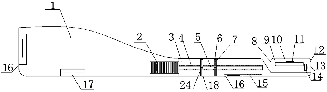
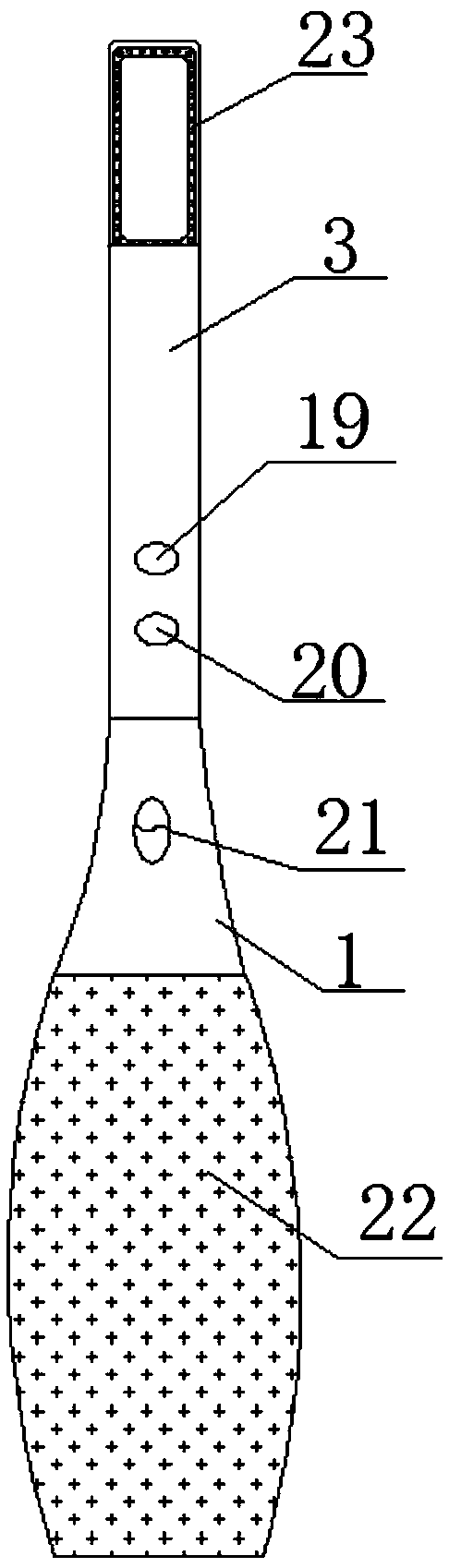
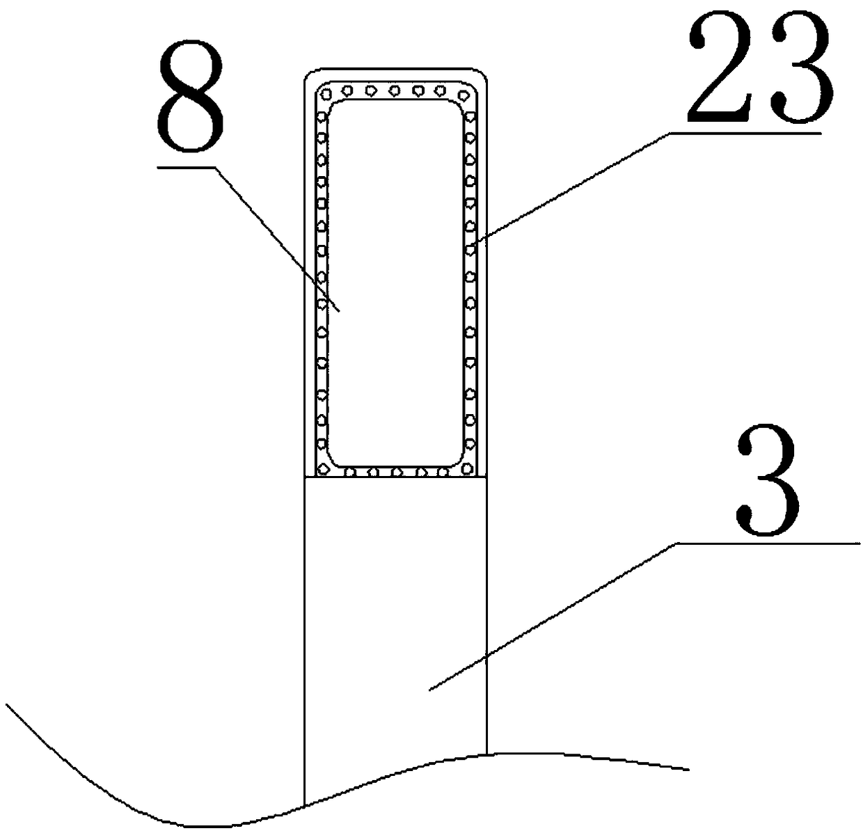
[0033] Such as figure 1 , figure 2 As shown, a rotary intraoral camera includes a handle 1 and a probe rod 3, which is characterized in that: a rotating shaft 5 is provided at the center of the top surface of the handle 1, and a rotating shaft 5 is provided at the center of the bottom surface of the probe rod 3. There is a rotating shaft groove 4 corresponding to the rotating shaft 5, the handle 1 and the probe rod 3 are detachably connected through the rotating shaft 5 and the rotating shaft groove 4, and the other end of the rotating shaft 5 extends through the top surface of the handle 1 to the handle 1 The interior is connected with the micro motor 2, and the upper end of the probe rod 3 is provided with a toothbrush head-shaped endoscope assembly 8 integrally formed with the probe rod 3, and the endoscope assembly 8 includes a plane mirror assembly 9 parallel to the probe rod 3 and A facade mirror assembly 12 perpendicular to the probe rod 3.

[0034] The working princ...

Embodiment 2

[0038] According to Example 1, such as figure 1 As shown, the plane mirror assembly 9 includes a plane eyepiece 10 and a plane camera 11 , and the elevation mirror assembly 12 includes an elevation eyepiece 13 and an elevation camera 14 . The arrangement of the plane mirror assembly 9 and the elevation mirror assembly 12 can observe and shoot the intraoral situation in different orientations simultaneously, which contributes to all-round observation.

Embodiment 3

[0040] According to Example 1, such as figure 1 As shown, the rotating shaft 5 is provided with several telescopic devices 18, the telescopic device 18 includes a telescopic slot 24 and a telescopic rod 7 fixed in the telescopic slot 24, and the telescopic device 18 in the shaft slot 4 and the rotating shaft 5 At corresponding positions, connecting grooves 6 are provided. The setting of the telescopic rod 7 can effectively prevent the handle 1 from slipping after the handle 1 is connected to the probe rod 3, and can play an auxiliary role in driving the rotation when the rotating shaft 5 drives the probe rod 3 to rotate.


PUM


Abstract

A rotary oral endoscope includes a handle and a probe, a rotating shaft is arranged at the central position of the top surface of the handle, a rotating shaft groove corresponding to the rotating shaft is arranged at the center position of the bottom surface of the probe rod, A handle and a probe rod are detachably connecte through a rotating shaft and a rotating shaft groove, The other end of therotating shaft extends through the top surface of the handle to the inside of the handle and is connected to the micro motor. The upper end of the probe rod is provided with a toothbrush head-like endoscope assembly integrally formed with the probe rod. The endoscope assembly includes a plane mirror assembly parallel to the probe rod and an elevation mirror assembly perpendicular to the probe rod. The invention can change the observation direction according to the actual need at any time, and omni-directionally observe the condition of each part in the oral cavity of the patient.

Description

technical field [0001] The invention relates to the technical field of endoscopes, in particular to a rotary oral endoscope. Background technique [0002] With the continuous updating of medical equipment, electronic intraoral camera is more and more widely used in major hospitals and outpatient clinics. The electronic intraoral camera lens is a specially constructed camera lens that can go deep into the oral cavity to take pictures, collect pictures or effects in the oral cavity, and transmit them to the display device to display clear and enlarged images on the display screen. With the assistance of the endoscopic system, the dentist can better discover the lesions that occur on the hard and soft tissue. [0003] In the prior art, the end of the intraoral camera is mostly equipped with a camera, and the intraoral camera is taken deep into the oral cavity to observe the oral cavity, but the oral cavity camera in the prior art is usually in the shape of a straight rod. The...

Claims


Application Information

Patent Timeline
Patent Type & Authority Applications(China)
IPC IPC(8): A61B1/247A61B1/06A61B1/04
CPCA61B1/247A61B1/04A61B1/0684
Inventor 邓述海
Owner 自贡德西玛医疗设备有限公司
Why Eureka
Try Eureka