
Fabric translation and traction mechanism

A technology of pulling mechanism and fabric, applied in fabric surface trimming, textile and paper making, fabric elongation, etc., can solve the problems of narrow application range, troublesome operation, complex structure, etc., and achieve the effect of reasonable structural design

Inactive Publication Date: 2019-01-08
桐乡市富利来针织股份有限公司
View PDF0 Cites 8 Cited by
  • Summary
  • Abstract
  • Description
  • Claims
  • Application Information

AI Technical Summary

Problems solved by technology

During the processing of the fabric, the fabric needs to be unfolded and pulled according to the specific processing needs of the fabric. Therefore, it is necessary to clamp and fix the end of the fabric and then pull the fabric horizontally. The existing fabric pulling mechanism has a complicated structure and The operation is cumbersome. In the process of pressing and fixing the end of the fabric, it is difficult for the existing pulling mechanism to press and fix the fabric conveniently and smoothly, and it is difficult for the existing fabric to be pulled according to the needs of the fabric during the translational pulling process. The pulling mechanism performs rotation adjustment and vertical lifting adjustment, which results in a narrow application range, reduces the efficiency and quality of fabric pulling, and cannot meet the needs of production and processing

Method used


Image

  • Fabric translation and traction mechanism
  • Fabric translation and traction mechanism
  • Fabric translation and traction mechanism

Examples


Embodiment Construction

[0015] In order to further describe the present invention, a specific implementation of a fabric translation and pulling mechanism will be further described below in conjunction with the accompanying drawings. The following examples are explanations of the present invention and the present invention is not limited to the following examples.

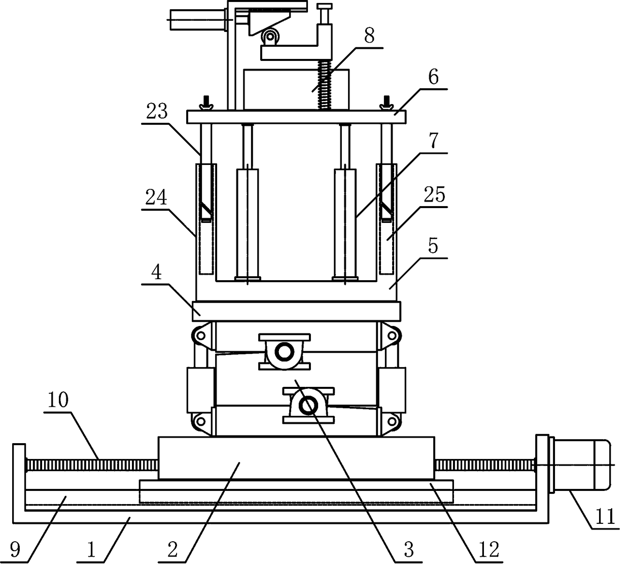
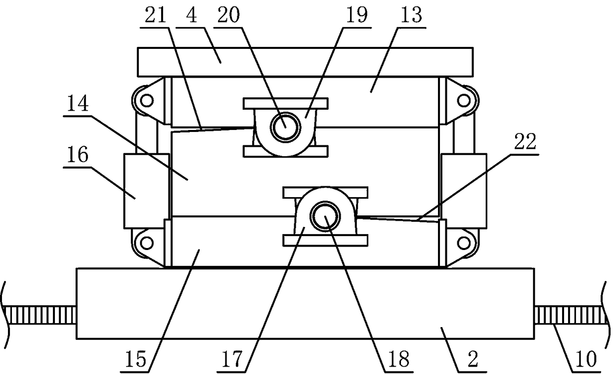
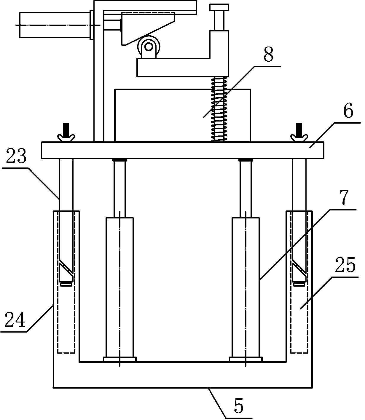
[0016] Such as figure 1 As shown, a fabric translation pulling mechanism of the present invention includes a translation bracket 1, a translation guide plate 2, a rotation adjustment mechanism 3, a rotation connecting plate 4, a lifting base 5, a lifting bracket 6, a lifting cylinder 7 and a cloth pressing mechanism 8. Both sides above the support 1 are respectively horizontally fixed with translation guide rails 9, and the upper middle part of the translation support 1 is horizontally connected with a translation screw rod 10, and the middle part of one side of the translation support 1 is horizontally fixed with a translation motor 11, a...


PUM


Abstract

The invention discloses a fabric translation and traction mechanism and belongs to the field of fabric processing mechanical equipment. A translation screw rod is in horizontal threaded connection with a translation guide plate; a rotation adjusting mechanism is arranged on the upper side of the translation guide plate; a rotation connecting plate is fixedly arranged on the upper side of the rotation adjusting mechanism; a lifting base is fixedly arranged on the upper side of the rotation connecting plate; a lifting bracket is arranged on the lifting base in a sliding manner in the vertical direction; a fabric pressing mechanism is fixedly arranged in the middle of the upper side of the lifting bracket; the output end of a lifting cylinder is fixedly connected with both sides of the lowerpart of the lifting bracket; a translation push block is arranged at the output end of a fabric pressing cylinder in a horizontal sliding manner; a fabric pressing inclined surface is arranged on thelower side of the translation push block in an inclined manner; both sides of a lifting pressing plate are arranged on the fabric pressing guide rod in the sliding manner in the vertical direction. The fabric translation and traction mechanism is reasonable in structure, an end part of a fabric can be conveniently and efficiently pressed and fixed, then the fabric can be stably and accurately translated and tracked, the processing automation degree of the fabric can be increased, and requirements of production and processing can be met.

Description

technical field [0001] The invention belongs to the field of textile fabric processing machinery and equipment, and in particular relates to a fabric translational pulling mechanism, which is mainly used for adjusting and pulling processing of various fabrics. Background technique [0002] With the continuous improvement of people's living standards, food, clothing, housing and transportation, as the most important part of people's lives, have been paid more and more attention to by people, and people are more and more advocating the pursuit of beauty, especially in dressing and dressing. There are also many kinds of fabrics, and the types and properties of fabrics are different. As one of the three elements of clothing, fabrics play a very important role in the clothing industry. Different fabrics have different roles and functions. Similarly, for example, knitted fabrics are fabrics formed by bending yarns into loops with knitting needles and interlacing them with each oth...

Claims


Application Information

Patent Timeline
Patent Type & Authority Applications(China)
IPC IPC(8): D06C3/00
CPCD06C3/00
Inventor 吴晨键
Owner 桐乡市富利来针织股份有限公司
Learn More