
Welding equipment

A technology of welding equipment and welding parts, applied in welding equipment, auxiliary welding equipment, welding/cutting auxiliary equipment, etc. Effect

Pending Publication Date: 2019-01-08
WUXI LEAD INTELLIGENT EQUIP CO LTD
View PDF0 Cites 2 Cited by
  • Summary
  • Abstract
  • Description
  • Claims
  • Application Information

AI Technical Summary

Problems solved by technology

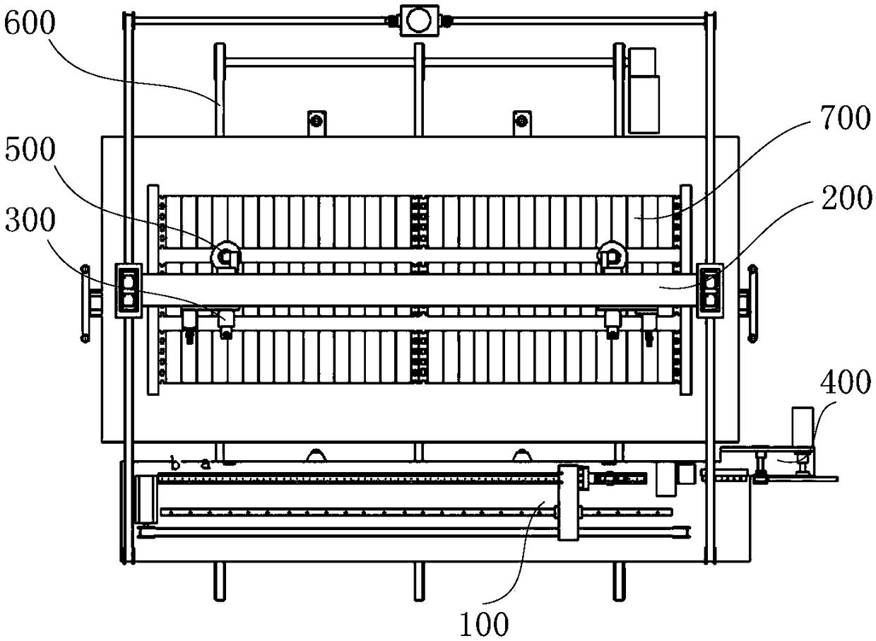
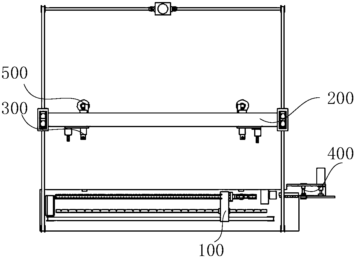
[0006] The purpose of the present invention is to provide a welding equipment to alleviate the problems of low welding precision and low efficiency in the prior art

Method used


Image

  • Welding equipment
  • Welding equipment
  • Welding equipment

Examples


Embodiment Construction

[0051]The technical solutions of the present invention will be clearly and completely described below in conjunction with the accompanying drawings. Apparently, the described embodiments are some of the embodiments of the present invention, but not all of them. Based on the embodiments of the present invention, all other embodiments obtained by persons of ordinary skill in the art without making creative efforts belong to the protection scope of the present invention.

[0052] In the description of the present invention, it should be noted that the terms "center", "upper", "lower", "left", "right", "vertical", "horizontal", "inner", "outer" etc. The indicated orientation or positional relationship is based on the orientation or positional relationship shown in the drawings, and is only for the convenience of describing the present invention and simplifying the description, rather than indicating or implying that the referred device or element must have a specific orientation, o...


PUM


Abstract

The invention provides welding equipment, and relates to the technical field of battery manufacturing equipment. The welding equipment comprises a welding strip pulling device, a welding strip conveying device and a welding device, wherein the welding strip pulling device is used for pulling out a welding strip from an unwinding device, the welding strip conveying device is used for transferring the pulled welding strip to a to-be-welded piece, and the welding device is used for welding the welding strip on the to-be-welded piece. The welding equipment solves the problems that the welding precision is low, and the efficiency is low in the prior art are solved.

Description

technical field [0001] The invention relates to the technical field of battery manufacturing equipment, in particular to welding equipment. Background technique [0002] The shingled module is a kind of interconnection method of solar cell modules. One side of one cell is stacked under the other cell, so that the grid lines on the front of the cell overlap with the electrodes on the back of the other cell. A conductive material is used between the electrodes to form a conductive connection. [0003] The manufacturing process of the shingled module is as follows: 1) Multiple battery slices are interconnected in sequence to form a battery string; 2) Terminal leads (for drawing current) are set at both ends of the battery string; 3) On a glass table covered with EVA film , a plurality of battery strings with terminal leads at both ends are typesetting to form a battery string; 4) Bus bars are arranged at both ends of the battery string, and the battery string and the glass tab...

Claims


Application Information

Patent Timeline
Patent Type & Authority Applications(China)
IPC IPC(8): B23K37/00B23K37/047H01L31/18
CPCH01L31/188B23K37/00B23K37/047Y02P70/50
Inventor 不公告发明人
Owner WUXI LEAD INTELLIGENT EQUIP CO LTD
Learn More