Molten material supply unit and dry coating device comprising same

A technology of molten material and supply unit, applied in metal material coating process, melt spraying, coating and other directions, can solve the problems of increasing processing cost, difficulty in continuous supply of solid raw materials, rising cost, etc., to achieve the effect of continuous supply

Inactive Publication Date: 2019-01-04
POHANG IRON & STEEL CO LTD
View PDF4 Cites 1 Cited by
  • Summary
  • Abstract
  • Description
  • Claims
  • Application Information

AI Technical Summary

Problems solved by technology

However, when using a raw material in the form of a wire rod, the processing cost for processing the shape of the raw material into a wire rod shape is increased, so there is a problem of cost increase. When using a liquid raw material, it is necessary to keep the exposed liquid raw material at a high temperature. There are limitations in the use of valves to control the supply of high-temperature liquid raw materials, so there is a problem that operating costs and equipment costs increase significantly
[0007] In particular, when a coating vapor is formed using a solid raw material and a coating operation is performed, there is a problem that it is difficult to continuously supply the solid raw material because the coating vapor flows countercurrently along the connecting pipe for supplying the solid raw material

Method used


Image

  • Molten material supply unit and dry coating device comprising same
  • Molten material supply unit and dry coating device comprising same
  • Molten material supply unit and dry coating device comprising same

Examples


Embodiment Construction

[0029] Hereinafter, specific embodiments of the present invention will be described in detail with reference to the accompanying drawings. However, the idea of ​​the present invention is not limited to the embodiments disclosed herein, and those skilled in the art who understand the idea of ​​the present invention can easily propose other backward components by adding, changing, or deleting other components within the same idea. Inventions or other embodiments included in the scope of the idea of ​​the present invention should also be included in the scope of the idea of ​​the present invention.

[0030] Also, components with the same functions within the same scope of thought shown in the drawings of the respective embodiments will be described using the same reference numerals.

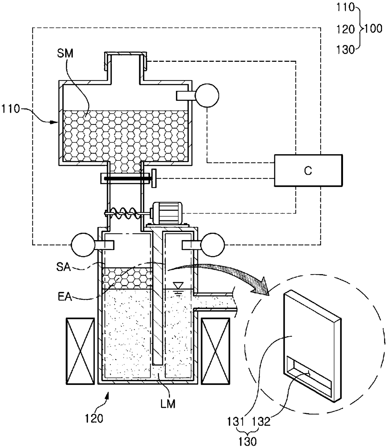
[0031] The present invention relates to a molten material supply unit 100 and a dry coating device including the supply unit. It is not necessary to process the gold-plated material into a wire or p...


PUM


Abstract

A molten material supply unit according to an embodiment of the present invention may comprise: a raw material supply portion to which a solid material is fed; a melting container portion connected tothe raw material supply portion so as to melt the solid material, thereby forming a molten material, and to discharge the molten material to the outside; and a barrier portion provided between a supply area of the melting container portion, which is connected to the raw material supply portion, and a discharge area of the melting containing portion, through which the molten material is dischargedto the outside, such that the molten material is solely moved to the discharge area. In addition, a dry coating device according to another embodiment of the present invention may comprise: the molten material supply unit; a vacuum chamber unit provided such that a to-be-plated member can move therein, the melting container portion of the molten material supply unit being provided inside the vacuum chamber unit; and a vapor spraying unit provided inside the vacuum chamber unit and connected to the melting container portion so as to heat the molten material, thereby forming a vapor material, and to spray the vapor material to the to-be-plated member, thereby coating the same.

Description

technical field [0001] The present invention relates to a molten material supply unit and a dry coating device including the supply unit. Background technique [0002] A coating substance such as metal vapor can be coated on the surface of a steel sheet by known various methods of depositing a continuously moving steel sheet in a vacuum atmosphere. Vacuum deposition based on the above-mentioned dry coating method is to vaporize and form a solid or liquid coating substance (metal or coating substance) by heating in a vacuum atmosphere by various methods and form it into a vapor, by which it is deposited on the steel sheet Form a thin film. [0003] More specifically, in the existing dry coating method, an electromagnetic coil for heating the coating substance is arranged in a vacuum chamber through which a member to be plated such as a steel plate continuously passes, and a high-frequency current is applied to the inside of the electromagnetic coil. The electromagnetic forc...

Claims


Application Information

Patent Timeline
Patent Type & Authority Applications(China)
IPC IPC(8): C23C4/00C23C14/24C23C4/12
CPCC23C14/243C23C14/246C23C14/562C23C4/00C23C4/12C23C14/24
Inventor 金句和林承昊金兑烨朴永善南庆勋
Owner POHANG IRON & STEEL CO LTD
Why Eureka
Try Eureka