Aircraft with load reducing wing like element

A technology for aircraft and components, applied in the field of aircraft, can solve the problems of small contour depth and thickness obstruction, and achieve the effect of reducing the total load

Active Publication Date: 2019-01-04
AIRBUS OPERATIONS GMBH +1
View PDF13 Cites 2 Cited by
  • Summary
  • Abstract
  • Description
  • Claims
  • Application Information

AI Technical Summary

Problems solved by technology

[0004] Additionally, the incorporation of relatively large control surfaces may be hampered by the often advantageous low profile depth and thickness in terms of aerodynamic performance

Method used


Image

  • Aircraft with load reducing wing like element
  • Aircraft with load reducing wing like element
  • Aircraft with load reducing wing like element

Examples


Embodiment Construction

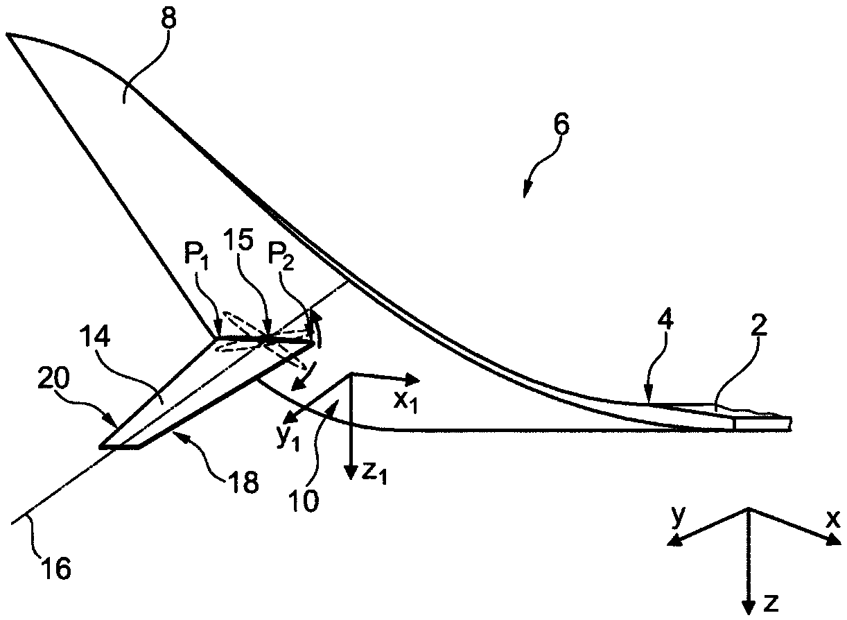
[0045] Figure 1a Shown is a wing 2 attached to the fuselage (not shown) of the aircraft, the wing 2 having a wing end 4 to which a wingtip arrangement 6 is mounted. Exemplarily, the wingtip device 6 comprises a planar winglet 8 and a curved transition region 10 extending between a connection region 12 of the planar winglet 8 and the wing end 4 of the wing 2 . The planar winglets 8 extend approximately at right angles to the xy plane of the aircraft. Due to aerodynamic and mass forces, the wingtip arrangement 6 generates additional structural loads on the aircraft structure depending on the actual flight conditions. Exemplarily, the wingtip arrangement 6 is shown in flight.

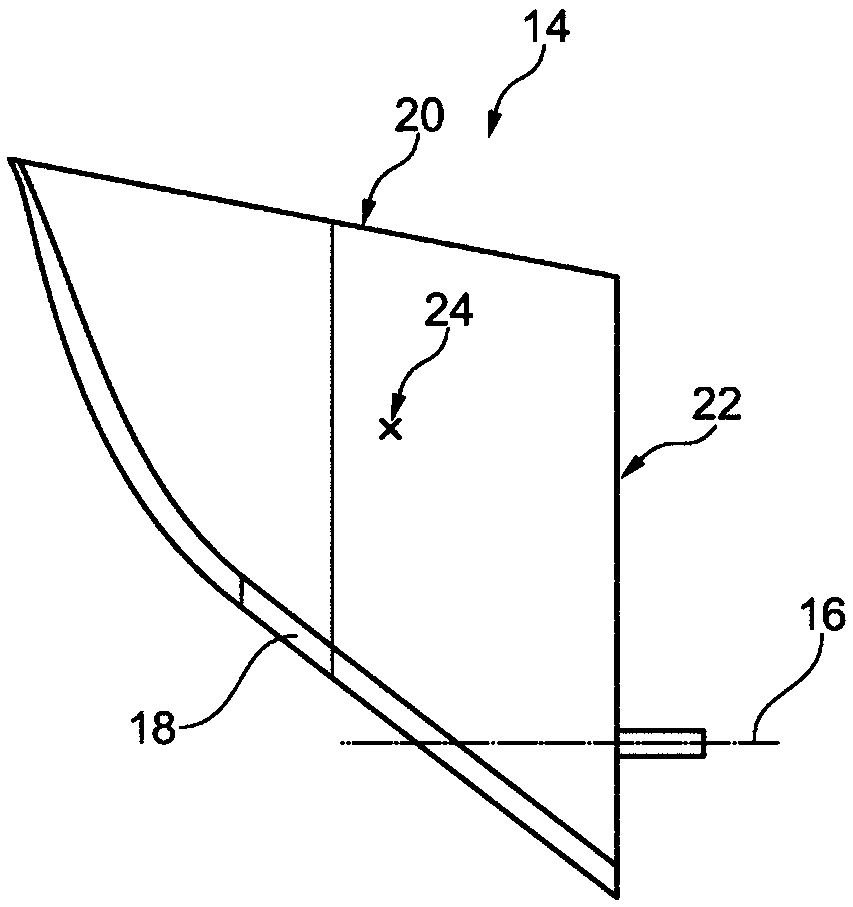
[0046] Exemplarily, the wing element 14 is arranged on the underside of the transition region 10 and extends in the spanwise direction, thereby resulting in an increase in the span. As indicated by the dotted line, the wing 14 is rotatable about an axis of rotation 16, which will be described in further...


PUM


Abstract

An aircraft comprises a fuselage, a wing (2) attached to the fuselage, a wing tip device (6) attached to a wing end (4) of the wing (2), at least one additional wing-like element (14) having a wing root (22), a wing leading edge (18) and a wing trailing edge (20), and a torque control device having a rotatable interface means. The torque control device is adapted for rotatably supporting the wingroot of the wing-like element on the interface means under creation of a rotational axis (16) extending from the interface means into the wing-like element (14), about which rotational the wing-like element (14) is rotatable. The wing-like element (14) is adapted to induce a rotation around the rotational axis (16) in an air flow. The torque control device is adapted to limit the degree of rotation depending on a torque introduced into the interface means by the wing-like element (14) and the wing root (22) of the at least one wing-like element (14) is coupled with at least one of the wing tipdevice (6), the wing (2) and the fuselage through the torque control device such that the leading edge (18) extends into an airflow surrounding the aircraft.

Description

technical field [0001] The invention relates to an aircraft having a fuselage; a wing attached to the fuselage; a wingtip arrangement of the wing attached to the wing; and at least one wing-like element. Background technique [0002] The large wingtip devices that are widely used on aircraft have the effect of increasing the structural loads, which lead to additional bending moments in the wing region, especially in the wing root region. A reduction or prevention of an increase in the maximum load on the aircraft, especially under the influence of gusts of wind or severe operating conditions, can be achieved by means of the load mitigation system. These load mitigation systems may comprise adjustable control surfaces located at the trailing edge of the wing or also in front of the wing section. Another possibility is to incorporate these control surfaces into wingtip devices. [0003] However, due to the fact that the control surfaces act at very large angles relative to t...

Claims


Application Information

Patent Timeline
Patent Type & Authority Applications(China)
IPC IPC(8): B64C3/56B64C5/08B64C23/06
CPCB64C3/56B64C5/08B64C23/065Y02T50/10B64C3/385B64C13/02
Inventor 弗兰克·特里奇扬·伊米什奇
Owner AIRBUS OPERATIONS GMBH
Why Eureka
Try Eureka