Robot control device
A technology of control devices and robots, applied in the direction of program control manipulators, manipulators, manufacturing tools, etc., which can solve problems such as reduced operating efficiency
- Summary
- Abstract
- Description
- Claims
- Application Information
AI Technical Summary
Problems solved by technology
Method used
Image


Examples
Embodiment approach 1
[0028] figure 1 It is a schematic diagram showing an example of a robot system including the robot control device 1 according to Embodiment 1 of the present invention and a work site to which the robot system is applied. figure 1 The robot controller 1 shown is connected to the robot 2, and outputs motion commands to the robot 2 based on the robot joint angle signal 3a from the robot joint angle measuring device 3 and the operation procedure specification signal 5a from the operation procedure specification device 5. In addition, in figure 1 In the shown work site, a workbench 6 is arranged and a worker 7 exists, and the robot 2 and the worker 7 share the work space and operate.
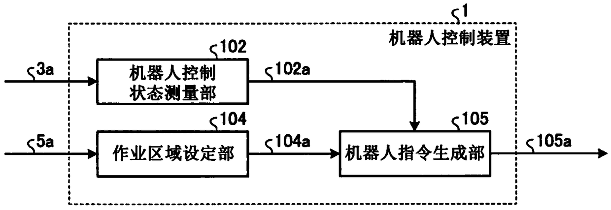
[0029] figure 2 yes means figure 1 A block diagram of a configuration example of the robot controller 1 shown. figure 2 The shown robot control device 1 has: a robot control state measurement unit 102 that measures the robot control state information 102a that is the position and posture of the...
Embodiment approach 2
[0048] In this embodiment, a mode in which the robot command generation unit in the robot controller operates to retreat the robot 2 from the work area will be described. Figure 5 It is a block diagram showing a configuration example of the robot controller 1A according to the present embodiment. Figure 5 The robot controller 1A shown replaces the figure 2 The robot command generation unit 105 shown has a robot command generation unit 105A.
[0049] Figure 6 yes means Figure 5 A block diagram of a configuration example of the robot command generation unit 105A shown. Figure 6 The shown robot command generating unit 105A has an evasive motion trajectory generating unit 108, instead of image 3 The illustrated operation command output unit 107 has an operation command output unit 107A.
[0050] Based on the robot control state information 102a, the retraction trajectory generator 108 generates retraction trajectory information 108a ranging from the current control sta...
Embodiment approach 3
[0063] In this embodiment, a description will be given of a mode in which the robot operates so as to retreat in advance from the work area next to the current work process of the operator.
[0064] Figure 8 It is a block diagram showing a configuration example of the robot controller 1B according to the present embodiment. exist Figure 8 in, right with figure 2 The structures that are the same as those shown are denoted by the same reference numerals and their descriptions are omitted. Figure 8 The Robot Controller 1B shown replaces the figure 2 The illustrated work area setting unit 104 has a work area setting unit 104B, and has a robot command generation unit 105B instead of the robot command generation unit 105 .
[0065] In the work area setting unit 104B, based on the work area in the work process, it is stored in accordance with the order of the next work process, and the work in the work area information 104a corresponding to the work process of the current op...
PUM
 Abstract
Description
Claims
Application Information
 - Generate Ideas
- Intellectual Property
- Life Sciences
- Materials
- Tech Scout
- Unparalleled Data Quality
- Higher Quality Content
- 60% Fewer Hallucinations
Browse by: Latest US Patents, China's latest patents, Technical Efficacy Thesaurus, Application Domain, Technology Topic, Popular Technical Reports.
© 2025 PatSnap. All rights reserved.Legal|Privacy policy|Modern Slavery Act Transparency Statement|Sitemap|About US| Contact US: help@patsnap.com