A photovoltaic energy storage system
A technology of photovoltaic energy storage and energy storage system, applied in the field of energy storage, can solve problems such as affecting the service life of battery packs, and achieve the effect of improving signal transmission capability and anti-interference performance, good high temperature performance, and ensuring reliable operation.
- Summary
- Abstract
- Description
- Claims
- Application Information
AI Technical Summary
Problems solved by technology
Method used
Image
Examples
Embodiment 1
[0029] The present invention provides such as Figure 1-2 A photovoltaic energy storage system shown includes a control terminal 1, a BMS system 2, a photovoltaic module board 5, and a power grid 6. The connection end of the control terminal 1 is connected to a BMS system 2, and the BMS system 2 is connected through an RS485 communication bus. There is a photovoltaic controller 3 and a grid-connected transformer 4, the input end of the photovoltaic controller 3 is connected to the photovoltaic module board 5 and the input end is connected to the first battery pack 6, the input end of the grid-connected transformer 4 is connected to the grid 7 and the output A second battery pack 8 is connected to the terminal, a first relay 9 is set between the photovoltaic controller 3 and the first battery pack 6, a third relay 11 is set between the first battery pack 6 and the BMS system 2, A second relay 10 is set between the grid-connected transformer 4 and the second battery pack 8, a fo...
Embodiment 2
[0034] Further, in the technical solution of Embodiment 1, the BMS system 2 includes a battery pack monitoring unit 21, a battery pack control unit 22, and an energy storage system management unit 23, and the battery pack monitoring unit 21 and the battery pack control unit 22 And the battery pack control unit 22 and the energy storage system management unit 23 are connected through signal lines, and the battery pack monitoring unit 21 is a BMM3.1 battery monitoring module, which can monitor and collect the battery pack operation information , charging equalization management and fault diagnosis are highly integrated in one, and the battery pack control unit 22 uses an ESGU battery pack control module, which can control the disconnection of the entire battery pack to prevent the battery from being overcharged, overdischarged and Overcurrent, the energy storage system management unit 23 is an ESMU type energy storage system management module, which is used to perform numerical c...
Embodiment 3
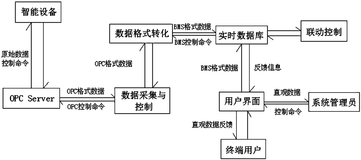
[0038] The present invention also provides image 3 A control method for a photovoltaic energy storage system is shown, and its specific operation steps are as follows:
[0039] S1: Send the raw data of the battery pack to the OPC Server of each battery pack through the smart device, and convert the data sent by the smart device into OPC-compliant data through the OPC Server, and provide a standard data interface at the same time;
[0040] S2: Call the data interface provided by the OPC Server through the data acquisition and control module to obtain the battery pack data that conforms to the OPC specification, convert the data into the same data format of the BMS, and store it in the real-time database;
[0041] S3: The linkage control module monitors the changes in the variable values in the real-time database. If it finds a variable change that meets the linkage conditions, it sends control commands to the real-time database according to the preset linkage controller. Ac...
PUM
 Abstract
Description
Claims
Application Information
 - R&D
- Intellectual Property
- Life Sciences
- Materials
- Tech Scout
- Unparalleled Data Quality
- Higher Quality Content
- 60% Fewer Hallucinations
Browse by: Latest US Patents, China's latest patents, Technical Efficacy Thesaurus, Application Domain, Technology Topic, Popular Technical Reports.
© 2025 PatSnap. All rights reserved.Legal|Privacy policy|Modern Slavery Act Transparency Statement|Sitemap|About US| Contact US: help@patsnap.com


