
Antenna tuning method and wireless terminal

A wireless terminal and main antenna technology, applied in the electronic field, can solve the problems of communication quality impact of terminal equipment, signal quality deterioration between wireless terminal and signal source, etc.

Active Publication Date: 2020-10-30
HISENSE VISUAL TECH CO LTD
View PDF8 Cites 0 Cited by
  • Summary
  • Abstract
  • Description
  • Claims
  • Application Information

AI Technical Summary

Problems solved by technology

[0003] At present, the antenna in the wireless terminal is generally fixed inside the wireless terminal, and the directivity of the antenna is greatly affected by the position of the antenna. When the position between the wireless terminal and the signal source is fixed, if the direction of the antenna of the wireless terminal is not optimal for receiving Direction will cause the signal quality between the wireless terminal and the signal source to deteriorate, and the communication quality of the terminal device will be affected

Method used


Image

  • Antenna tuning method and wireless terminal
  • Antenna tuning method and wireless terminal
  • Antenna tuning method and wireless terminal

Examples


Embodiment Construction

[0039] In order to better understand the above technical solution, the above technical solution will be described in detail below in conjunction with the accompanying drawings and specific implementation methods. It should be understood that the embodiments of the present application and the specific features in the embodiments are detailed descriptions of the technical solution of the present application. To illustrate, rather than limit, the technical solutions of the present application, the embodiments of the present application and the technical features in the embodiments can be combined without conflict.

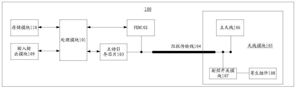
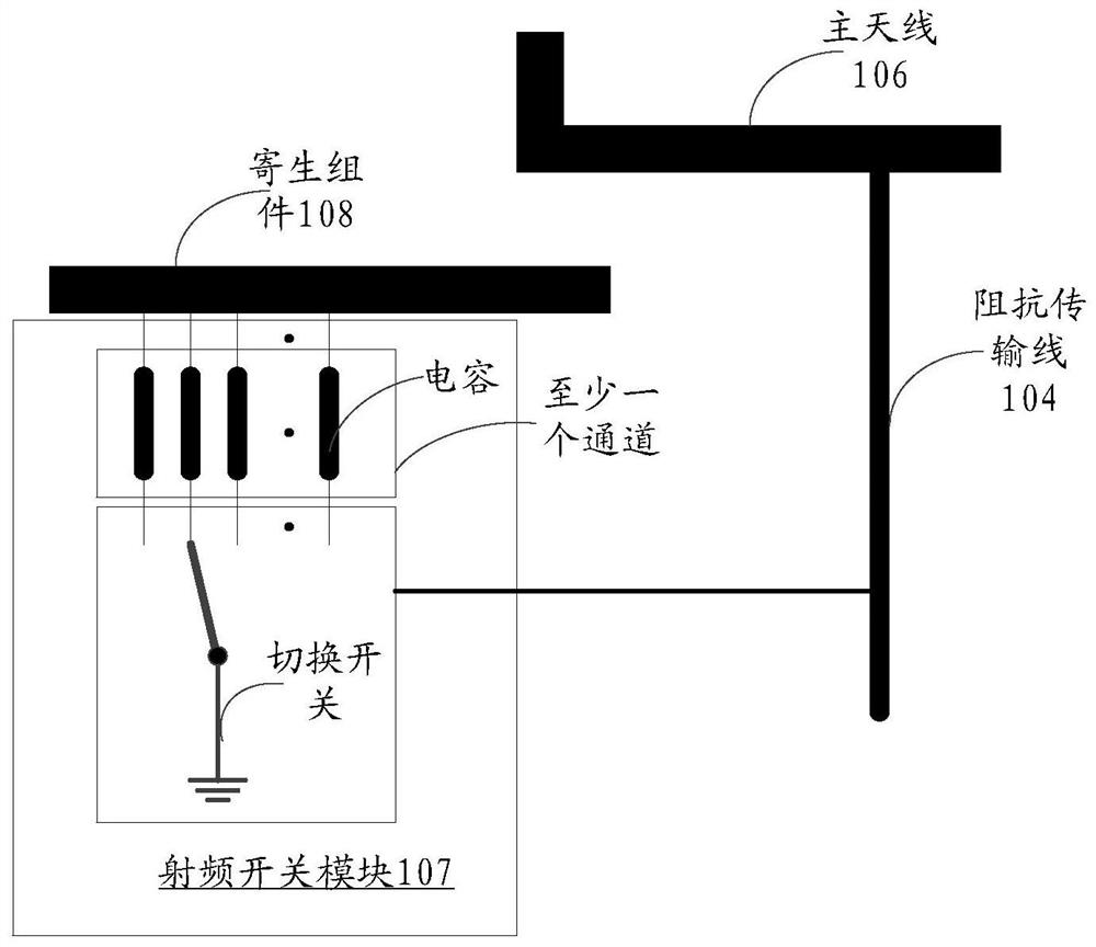
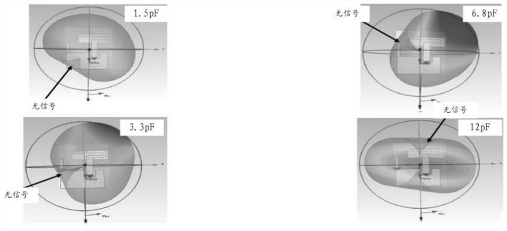
[0040] In the embodiment of the present invention, the wireless terminal is a device with a wireless transceiver function or a chip that can be set in the device. In practical applications, the wireless terminal in the embodiment of the present application may be a TV, a mobile phone (mobile phone), a tablet computer (Pad), a computer with a wireless transceiver functi...


PUM


Abstract

Disclosed in the present invention are an antenna tuning method and a wireless terminal, comprising: an antenna module comprising: a main antenna and a parasitic assembly of the main antenna. The main antenna is electrically connected to a radio frequency front end module by means of a radio frequency impedance transmission wire. The parasitic assembly is electrically connected to the radio frequency impedance transmission wire by means of a first channel electrically connected to a radio frequency switch module. The first channel is a channel among at least one channel between the parasitic assembly and the radio frequency switch module. The wireless terminal further comprises a processing module used to detect wireless signals received from the antenna module, and when a signal indication value of the wireless signal is lower than a threshold value, the processing module switches the switch module to a second channel to cause the parasitic assembly to be electrically connected with the radio frequency impedance transmission wire by means of the second channel. The second channel is a channel having the largest signal indication value of the corresponding wireless signal among the at least one channel.

Description

technical field [0001] The present invention relates to the field of electronic technology, in particular to an antenna tuning method and a wireless terminal. Background technique [0002] With the development of wireless communication technology, the performance of processors and radio frequency modules in wireless terminals has been greatly improved. However, with the development of miniaturization of wireless terminals, it has brought challenges to the design of antennas in wireless terminals. The quality of the performance determines the communication quality of the wireless terminal communication. [0003] At present, the antenna in the wireless terminal is generally fixed inside the wireless terminal, and the directivity of the antenna is greatly affected by the position of the antenna. When the position between the wireless terminal and the signal source is fixed, if the direction of the antenna of the wireless terminal is not optimal for receiving Direction will cau...

Claims


Application Information

Patent Timeline
Patent Type & Authority Patents(China)
IPC IPC(8): H01Q3/00H01Q3/24H01Q3/34
CPCH01Q3/00H01Q3/24H01Q3/34
Inventor 陈浩王海涛
Owner HISENSE VISUAL TECH CO LTD
Learn More