Interference reflection type optical film microscopic measurement method based on structured light

An optical thin film and microscopic measurement technology, applied in the field of optical imaging, can solve the problems of high detection cost, small scope of application, limited accurate determination, etc., and achieve the effects of improving imaging resolution, expanding spectrum range, and improving imaging contrast.

Active Publication Date: 2019-01-04
UNIV OF ELECTRONIC SCI & TECH OF CHINA
View PDF5 Cites 14 Cited by
  • Summary
  • Abstract
  • Description
  • Claims
  • Application Information

AI Technical Summary

Problems solved by technology

[0004] Aiming at the problems of high complexity, high detection cost, small scope of application, and limited accuracy in the detection method of the number of optical film layers on the traditional transparent substrate, the present invention proposes an interference reflective optical film based on structured light The microscopic measurement method, based on the IRM microscope structure and method, uses structured light instead of traditional light sources, and combines the information processing method of structured light, which has the advantages of simple operation, wide application range and high accuracy

Method used


Image

  • Interference reflection type optical film microscopic measurement method based on structured light
  • Interference reflection type optical film microscopic measurement method based on structured light
  • Interference reflection type optical film microscopic measurement method based on structured light

Examples


Embodiment 1

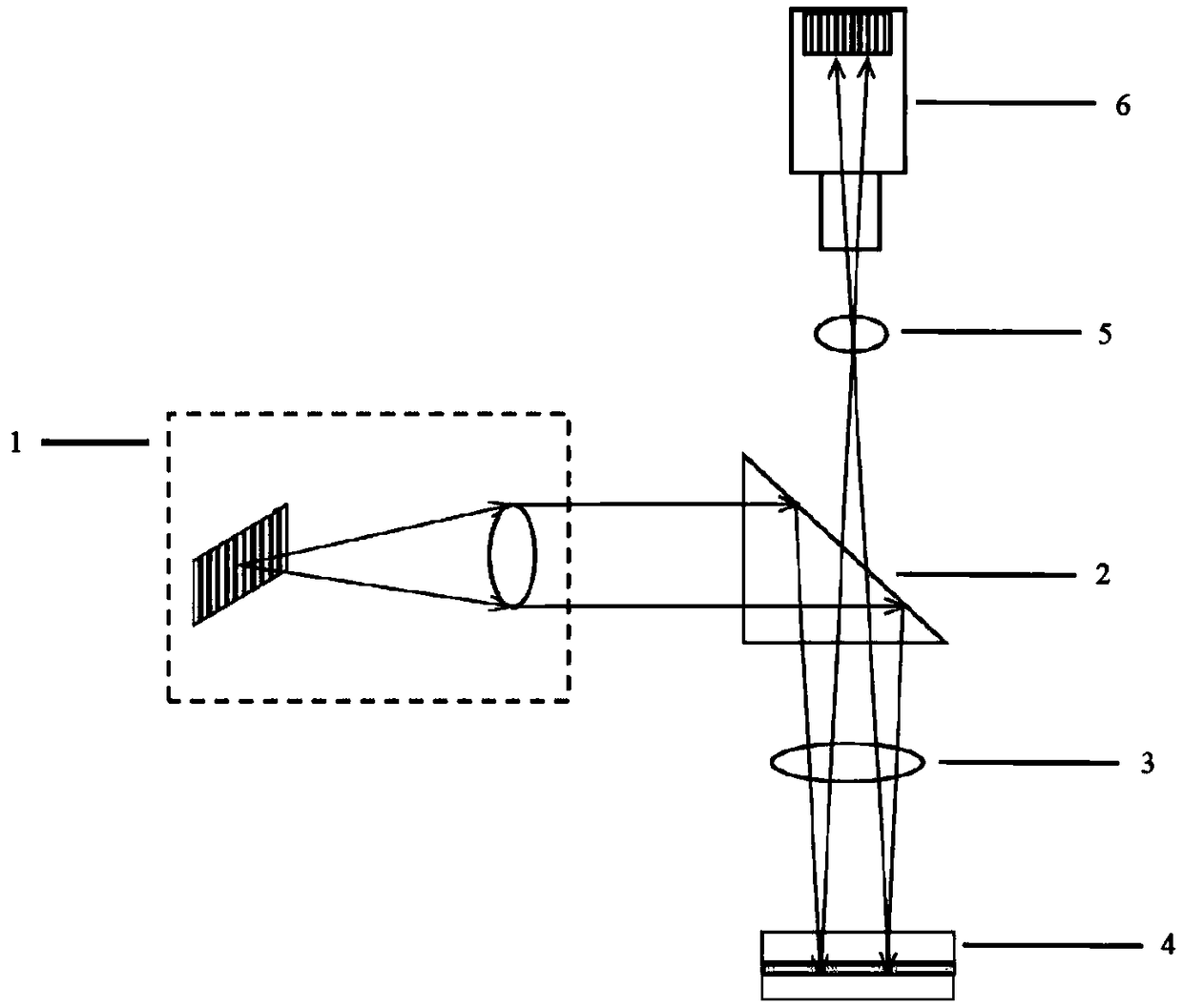
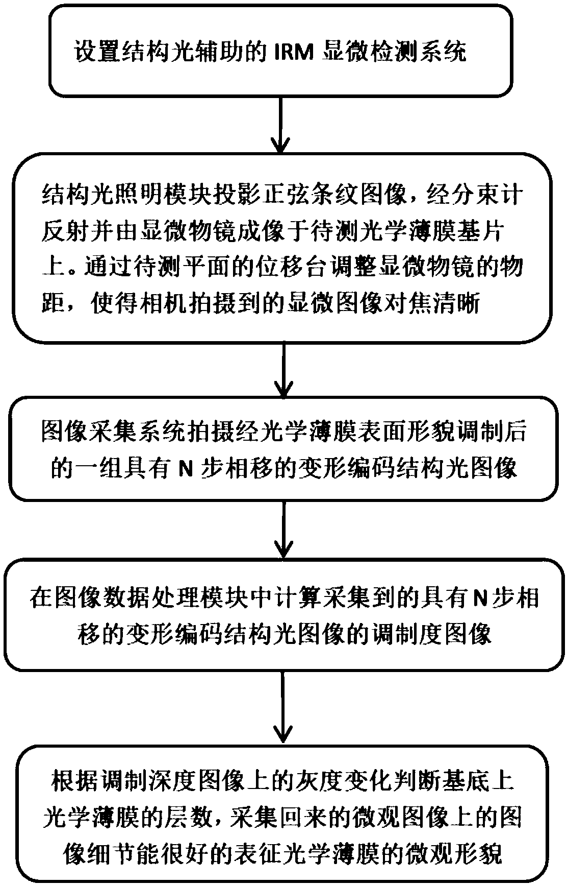
[0034] Embodiment 1: Encoded structured light with phase shift Take the standard N-step phase-shifted sinusoidal fringe light as an example, such as image 3 Shown is a schematic flow chart of detecting the surface morphology and the number of layers of an optical thin film using standard N-step phase-shifted sinusoidal fringe light. The specific method is:

[0035] The structured light lighting module uses a 12.78mm×9mm high-brightness micro-OLED display. The structured light lighting module 1 also includes a collimation module connected to the collimated micro-display. Since the micro-OLED lighting needs to ensure the imaging effect, it uses The 35mm lens is collimated to ensure that the structured light lighting module 1 can produce converging structured light; the micro-OLED display changes the pattern of the projected striped structured light with the computer signal, and the micro-OLED display is controlled by the computer to change the pattern of different phases at a ce...

Embodiment 2

[0068] Embodiment 2: Encoded structured light without phase shift Taking the non-phase-shifted striped light as an example, the method of obtaining the surface morphology and the number of layers of an optical film by using the non-phase-shifted striped light is as follows:

[0069] Also use the micro-OLED display to generate the striped structured light, but in this embodiment the micro-OLED display only projects one frame of sinusoidal striped images, and this image is collected in the image acquisition module 6 . A two-dimensional coordinate axis in the xy direction is established in the deformed interference pattern, and the light intensity information I(x, y) at the coordinate (x, y) in the deformed interference pattern contains phase information related to the height of the object and the surface reflectance Such as formula (10).

[0070]

[0071] In formula (10) is the real phase change caused by the height of the optical film and the surface reflectivity, f x an...


PUM


Abstract

The invention relates to an interference reflection type optical film microscopic measurement method based on structured light, and belongs to the technical field of optical imaging. The method comprises the steps of first, using the structured light as a light source, and enabling the structured light to passes through a microscope objective and then irradiate on the surface of a sample to be measured, wherein the sample to be measured comprises a transparent substrate and an optical film, the optical film includes a plurality of optical film layers, the structured light passes through the transparent substrate of the sample to be measured and is then reflected on the multiple optical film layers of the optical film, the reflected light of all optical film layers forms multi-beam interference and forms an interference pattern on the surface of the transparent substrate, and a clear interference pattern is formed on the surface of the transparent substrate through adjusting the distance between the microscope objective and the sample to be measured; and second, shooting a deformed interference pattern formed by amplifying the interference pattern on the surface of the transparent substrate through the microscope objective, and determining the number or surface morphology of the film layers at corresponding parts of the optical film according to collected light intensity information of each part in the deformed interference pattern. The interference reflection type optical film microscopic measurement method based on the structured light is accurate, simple, fast and wide inapplication range.

Description

technical field [0001] The invention belongs to the technical field of optical imaging, in particular to an interference reflection optical film microscopic measurement method and system using structured light illumination. Background technique [0002] Graphene (Gr) is a new material with high conductivity, high toughness, high strength, and large specific surface area. It is widely used in the fields of electronics, aerospace industry, new energy, and new materials. However, graphene films There has been a lack of a fast, efficient and accurate detection method for the number of layers and microscopic morphology. Generally, there are four methods for detecting the number of graphene-like optical film layers: optical microscopy, atomic force microscopy, transmission electron microscopy, and Raman spectroscopy. The optical microscope detection method is simple and fast, and does not cause damage to the sample, but it is limited to substrates with obvious contrast difference...

Claims


Application Information

Patent Timeline
IPC IPC(8): G01B9/04G01B9/02G01B11/24G06K9/00
CPCG01B9/02025G01B9/02043G01B9/02044G01B9/02091G01B9/04G01B11/2441G06V20/69
Inventor 岳慧敏周政宋一平方宇耀黄易杨刘永
Owner UNIV OF ELECTRONIC SCI & TECH OF CHINA
Why Eureka
Try Eureka