
Damper and overspeed testing machine with damper

A damper and damping technology, applied in the field of mechanical vibration reduction, can solve problems such as the inability to guarantee the safety of ultra-high-speed testing machines

Pending Publication Date: 2019-01-04
ZHUHAI GREE INTELLIGENT EQUIP CO LTD +1
View PDF0 Cites 0 Cited by
  • Summary
  • Abstract
  • Description
  • Claims
  • Application Information

AI Technical Summary

Problems solved by technology

[0004] The main purpose of the present invention is to provide a damper and an overspeed testing machine with it, so as to solve the problem that the damper in the prior art cannot guarantee the safety of an ultrahigh speed testing machine

Method used


Image

  • Damper and overspeed testing machine with damper
  • Damper and overspeed testing machine with damper
  • Damper and overspeed testing machine with damper

Examples


Embodiment Construction

[0039] It should be noted that, in the case of no conflict, the embodiments in the present application and the features in the embodiments can be combined with each other. The present invention will be described in detail below with reference to the accompanying drawings and examples.

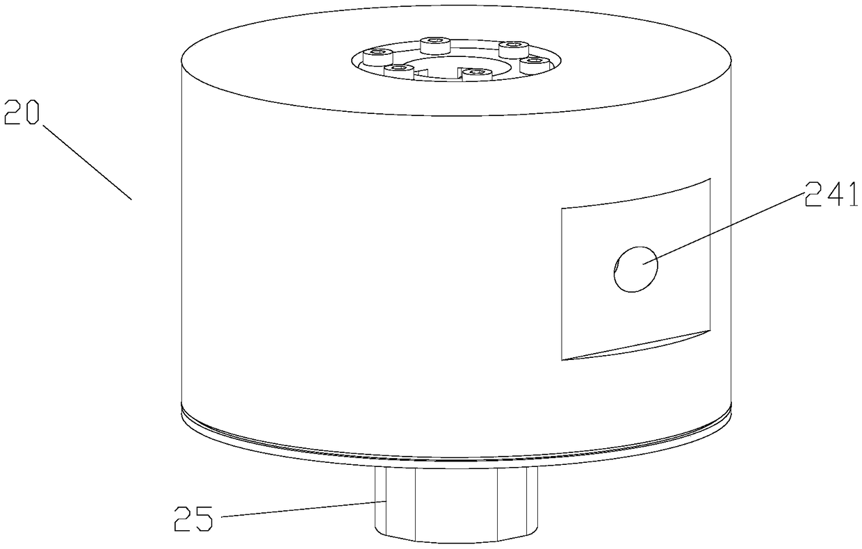
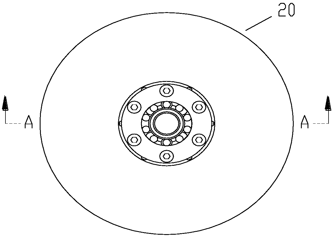
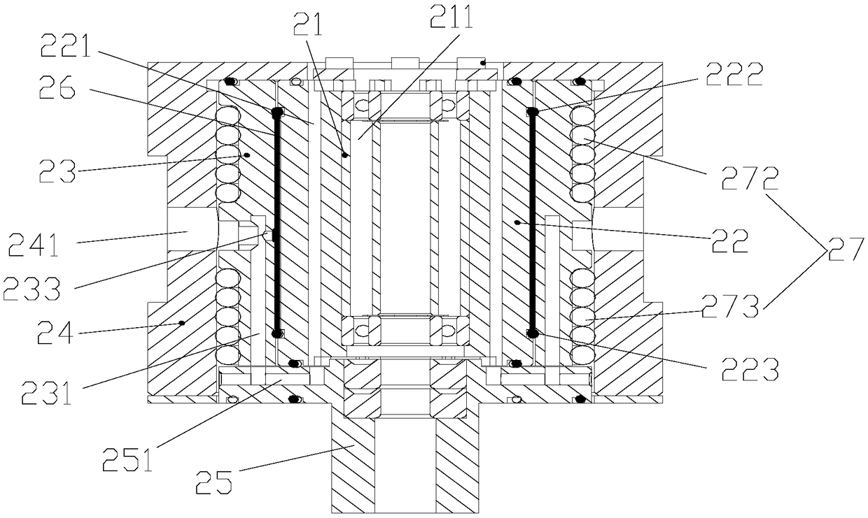
[0040] The present invention provides a damper, such as Figure 1 to Figure 14 , including: a housing 24, the core rod 100 is installed in the housing 24; a damping spacer 21, the damping spacer 21 is arranged in the housing 24 to reduce the vibration of the core rod 100; a damping seat 25, a damping seat 25 It is arranged in the casing 24 and connected with the damping spacer 21 ; the detection device is arranged on the casing 24 and detects the vibration of the core rod 100 by detecting the vibration of the damping seat 25 .

[0041] The damper provided by the present invention can be applied on an overspeed testing machine to damp the core rod 100. The damper includes a housing 24, a dampin...


PUM


Abstract

The invention provides a damper and an overspeed testing machine with the damper. The damper comprises a shell, a damping spacer bush, a damping seat and a detecting device. A core rod penetrates in the shell. The damping spacer bush is arranged in the shell so that vibration of the core rod can be reduced. The damping seat is arranged in the shell and is connected with the damping spacer bush. The detecting device is arranged on the shell and detects vibration of the core rod by detecting vibration of the damping seat. By means of the damper, the problem that in the prior art, a damper cannotensure safety of the overspeed testing machine is solved.

Description

technical field [0001] The invention relates to the field of mechanical vibration reduction, in particular to a damper and an overspeed testing machine with the same. Background technique [0002] At present, most of the existing traditional impeller overspeed testing machines are directly driven by motors or belt drives, and the speed is generally only between 10000r / min and 25000r / min. 40000r / min. At this time, the test has strict requirements on the vibration of the equipment during operation. If the vibration is too high, it needs to be forced to stop, otherwise it will easily cause damage to the equipment and even lead to safety accidents. [0003] In the existing equipment, devices such as dampers are generally used to slow down and absorb the vibration of the equipment, but the vibration absorption effect of the damper in the existing equipment is not good, and it affects the rotation speed and power consumption of the test piece, so it can only be adapted to lower sp...

Claims


Application Information

Patent Timeline
Patent Type & Authority Applications(China)
IPC IPC(8): F16F15/124G01M13/00
CPCF16F15/124G01M13/00
Inventor 冯东闯朱燕昌张秀峰黄静夷刘超
Owner ZHUHAI GREE INTELLIGENT EQUIP CO LTD
Learn More