Locking device, single-door drive system and double-door drive system

A locking device and transmission system technology, applied in power transmission/actuator features, electric locks, building locks, etc., can solve the problems of low reliability, high maintenance frequency, easy wear of pins, etc., and achieve low machining accuracy , High maintainability, and the effect of ensuring reliability

Active Publication Date: 2019-01-04
713 RES INST OF CHINA SHIPBUILDING IND CORP
View PDF14 Cites 0 Cited by
  • Summary
  • Abstract
  • Description
  • Claims
  • Application Information

AI Technical Summary

Problems solved by technology

[0004] (1) Low reliability: the overall structure of the locking device currently used in the industry is complex, and the installation accuracy is relatively high, which reduces the reliability of the locking device;
[0005] (2) Short service life: At present, the pin shaft in the locking device in the industry has to slide along the groove of the ball screw during the process of opening and closing the door, so the diameter of the pin shaft is limited, so that the pin shaft is easy to wear and reduces the locking effect. Device life
[0006] Poor maintainability: Due to the complex structure of the locking device, easy to wear and other shortcomings, the maintenance period of the equipment is long, the maintenance frequency is high, and the maintenance cost is expensive.

Method used


Image

  • Locking device, single-door drive system and double-door drive system
  • Locking device, single-door drive system and double-door drive system
  • Locking device, single-door drive system and double-door drive system

Examples


Embodiment Construction

[0054] The present invention will be described in further detail below in conjunction with the accompanying drawings and specific embodiments.

[0055] The invention provides a locking device for a train plug door system based on the principle of self-locking. The locking device can be driven by forward and reverse rotation of a screw rod to open and close the plug door.

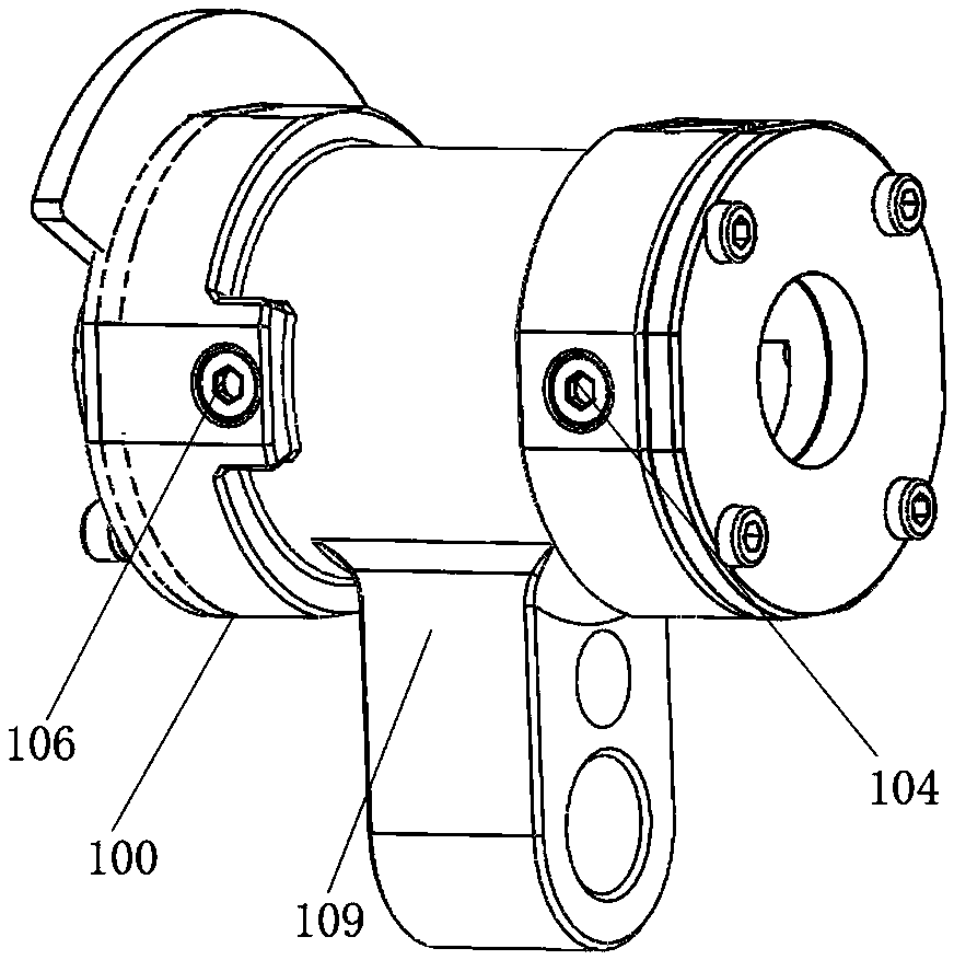
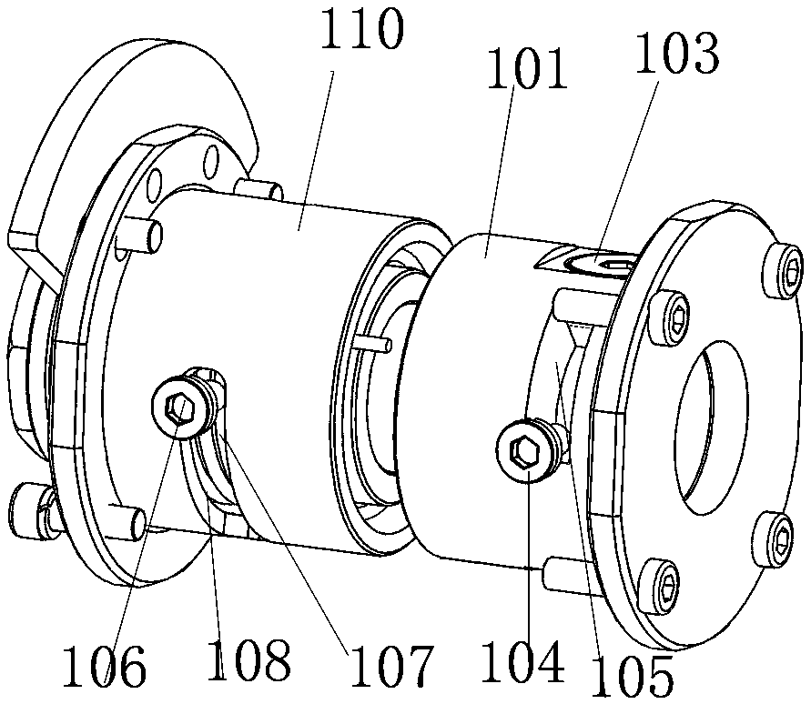
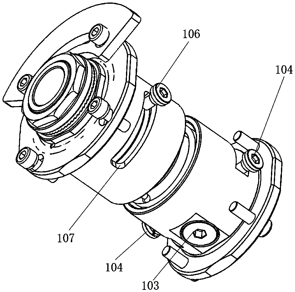
[0056] Such as Figure 1~4 As shown, the device of the present invention includes a screw rod 5, and the door lock device 100 is installed on the screw rod 5, and operates with the rotation of the screw rod.

[0057] Specifically, the door lock device includes a locking block adjacent to the nut pair of the screw mandrel 5, and the locking block can move axially with the nut pair on the screw mandrel 5; the nut pair is an inherent device on the screw mandrel 5, The nut pair can move on the screw mandrel 5 under the rotation of the screw mandrel 5 . It also includes a locking groove provided on the screw ro...


PUM


Abstract

The invention discloses a locking device. The locking device comprises a screw rod, and a door lock device is arranged on the screw rod; the door lock device comprises a locking block and a locking clamping groove, wherein the locking block is adjacent to a nut pair of the screw rod, and the locking clamping groove is formed in the screw rod; the locking block is screwed into the locking clampinggroove for axial locking under the rotation of one direction of the screw rod, and the locking block is screwed out of the locking clamping groove to carry out axial unlocking under the rotation of the other direction of the screw rod; the locking clamping groove comprises a step surface arranged on an polished shaft of the screw rod, and an arc-wedge-shaped clamping groove which is connected withthe step surface; and door lock supports which are rotationally connected with a sliding plug door are arranged outside the nut pair and the locking block. According to the locking device, the single-door drive system and the double-door drive, the automatic locking function and the unlocking function can be reliably completed; and in addition, the locking device further has the advantages of being few in parts, low in machining precision, simple in structure, and high in maintainability.

Description

technical field [0001] The invention relates to a locking device for a sliding door, in particular to a locking device for a train sliding door system based on a self-locking principle, a single door transmission system, and a double door transmission system. Background technique [0002] With the rapid development of my country's urban rail transit, the demand for urban rail vehicles, including subways, light rails, and trams, continues to increase, and the operating speed continues to accelerate. The main goal of urban rail vehicles is to quickly and safely transport a large number of passengers. The train sliding door is an important part of the rail vehicle, which directly affects the normal operation of the vehicle and the safety and sealing of passengers. It mainly involves machinery, electricity, software, Signaling, communication and other technologies; the locking device is one of the two key core systems in the train sliding door system. The safety, reliability and...

Claims


Application Information

Patent Timeline
Patent Type & Authority Applications(China)
IPC IPC(8): E05B83/40E05B81/06E05B81/40
CPCE05B81/06E05B81/40E05B83/40
Inventor 郝登运王永刚王建楹巩奇李效普朱伟李凡营
Owner 713 RES INST OF CHINA SHIPBUILDING IND CORP
Why Eureka
Try Eureka