A three-finger non-cooperative target capture mechanism and its capture method
A non-cooperative target and finger technology, which is applied to the three-finger non-cooperative target capture mechanism and its capture field, can solve the problems of large volume and heavy weight, and achieve the effect of small volume, light weight and reduced collision force
- Summary
- Abstract
- Description
- Claims
- Application Information
AI Technical Summary
Problems solved by technology
Method used
Image
Examples
specific Embodiment approach 1
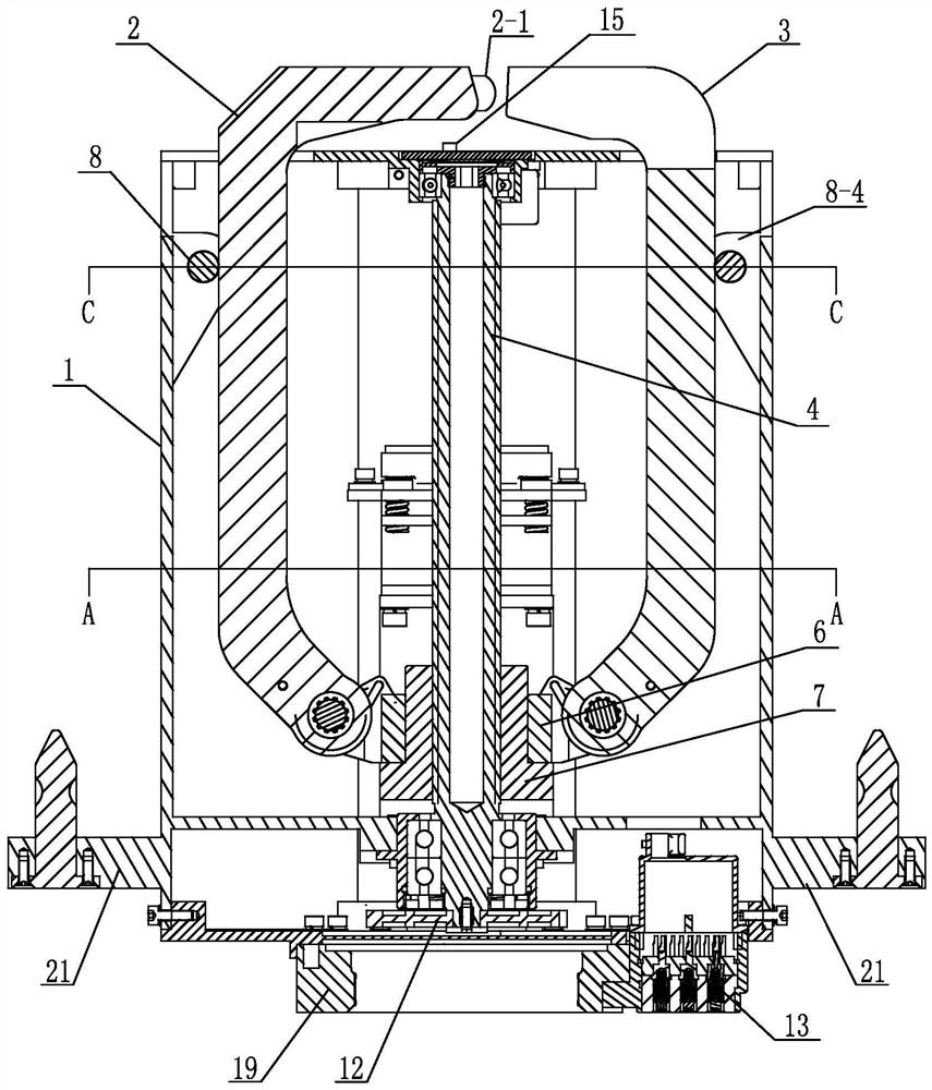
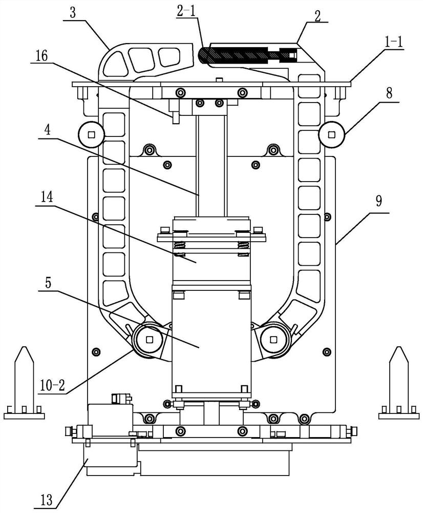
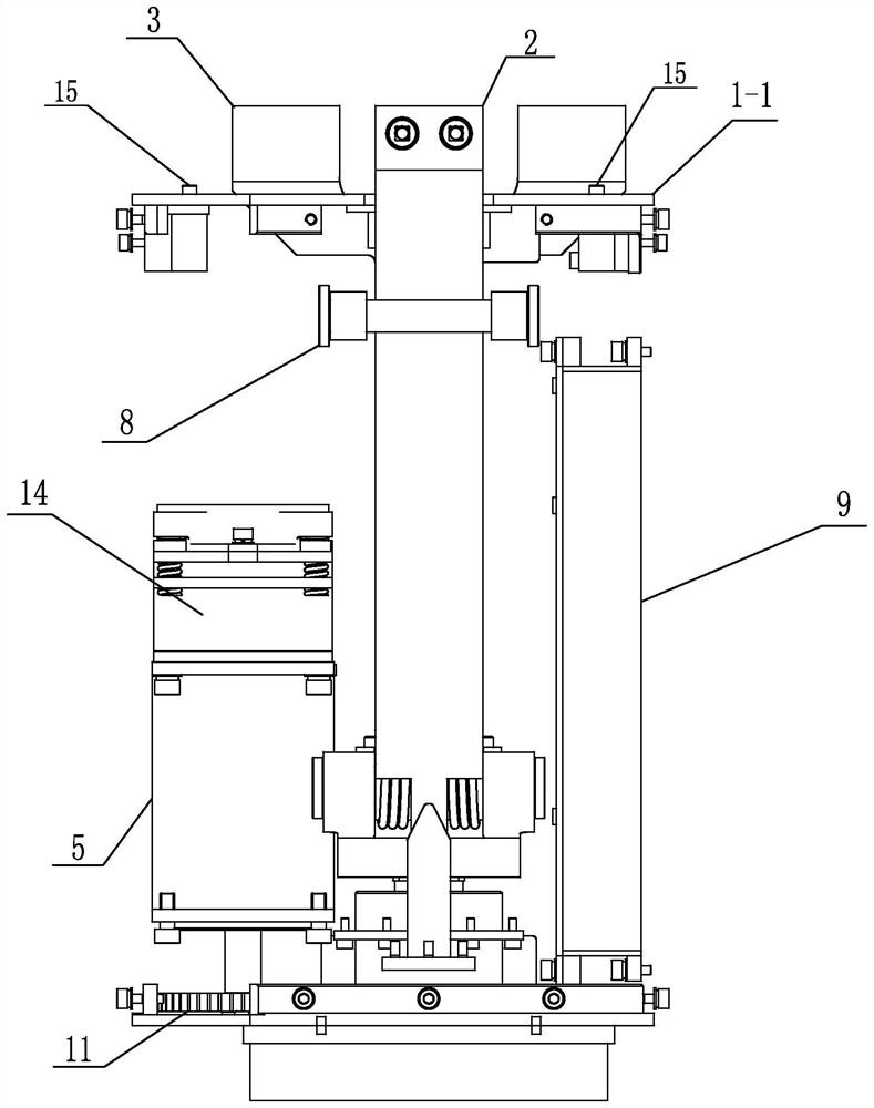
[0033] Specific implementation mode one: combine Figure 1-14 To illustrate this embodiment, the three-finger non-cooperative target capture mechanism described in this embodiment includes a housing 1, a driving device, a ball screw shaft 4, a screw nut 7, an adapter 6 and a capture finger;
[0034] Such as figure 1 , 4 As shown: the housing 1 includes a support wall 1-4, an upper cover plate 1-1, a lower bottom plate 1-2, a support plate 1-3 and a connecting ear plate 21; the upper cover plate 1-1 buckles At the upper end of the support wall 1-4, the lower bottom plate 1-2 is at the bottom end of the support wall 1-4, and the support plate 1-3 is at the inner lower position of the support wall 1-4; the support plate 1-3 and The supporting wall 1-4 is integrally formed, and there are two connecting lugs 21, which are respectively arranged on both sides of the supporting wall 1-4; the guide pin fixes the housing on the platform through the pin holes on the connecting lugs;
...
specific Embodiment approach 2
[0043] Specific implementation mode two: combination Figure 6-8 , 10 illustrates this embodiment, the adapter 6 described in this embodiment has four corners, each corner is connected with a cylindrical insert 6-1, and there is a large jack in the cylindrical insert 6-1; A slot 6-1-1 is formed between two cylindrical inserts 6-1 oppositely arranged on the same side; there is a triangular insert 6 at the upper end of the connection between each cylindrical insert 6-1 and the adapter 6 -2; the triangular insert 6-2 has a small jack; the adapter 6, the cylindrical insert 6-1 and the triangular insert 6-2 are integrally formed;
[0044] A hinge 10 is installed between the two cylindrical inserts 6-1 oppositely arranged on the same side.
[0045] Other composition and connection methods are the same as those in Embodiment 1.
specific Embodiment approach 3
[0046] Specific implementation mode three: combination Figure 1-5 , 9, 10, 12, and 13 illustrate this embodiment. The capture finger described in this embodiment includes an inner capture finger 2 and an outer capture finger 3; The two sides of the part 6; the gaps at the two ends of the upper cover plate 1-1 and the two side gaps at the upper end of the support wall 1-4 form two telescopic holes, which are respectively the first telescopic holes 1-1- 1 and the second telescopic hole 1-1-2; the capture end of the inner capture finger 2 extends out of the support wall 1-4 through the first telescopic hole 1-1-1, and the capture end of the outer capture finger 3 passes through the second telescopic hole 1 - 1-2 protrude from the support wall 1-4.
[0047] Other compositions and connection methods are the same as those in Embodiment 1 or 2.
PUM
 Abstract
Description
Claims
Application Information
 - R&D
- Intellectual Property
- Life Sciences
- Materials
- Tech Scout
- Unparalleled Data Quality
- Higher Quality Content
- 60% Fewer Hallucinations
Browse by: Latest US Patents, China's latest patents, Technical Efficacy Thesaurus, Application Domain, Technology Topic, Popular Technical Reports.
© 2025 PatSnap. All rights reserved.Legal|Privacy policy|Modern Slavery Act Transparency Statement|Sitemap|About US| Contact US: help@patsnap.com


