A contact state monitoring device between a shaft retaining ring and a shaft groove

A shaft retaining ring and contact state technology, which is applied in the field of contact state monitoring devices between the shaft retaining ring and the shaft groove, can solve the problems that it is difficult to monitor the contact state of the shaft retaining ring and the shaft groove, and achieve strong implementability and low occupation cost. The effect of small space and small quality

Active Publication Date: 2020-08-14
HEFEI UNIV OF TECH
View PDF7 Cites 0 Cited by
  • Summary
  • Abstract
  • Description
  • Claims
  • Application Information

AI Technical Summary

Problems solved by technology

[0009] The technical problem to be solved by the present invention lies in the fact that the existing technology is difficult to monitor the contact state of the shaft retaining ring and the shaft groove under the state of high-speed rotation

Method used


Image

  • A contact state monitoring device between a shaft retaining ring and a shaft groove
  • A contact state monitoring device between a shaft retaining ring and a shaft groove
  • A contact state monitoring device between a shaft retaining ring and a shaft groove

Examples


Embodiment 2

[0043] In this embodiment, based on the monitoring device for the contact state between the shaft retaining ring and the shaft groove in Embodiment 1, the monitoring experiment of the contact state between the Φ60mm and Φ100mm shaft retaining ring and the shaft groove is carried out.

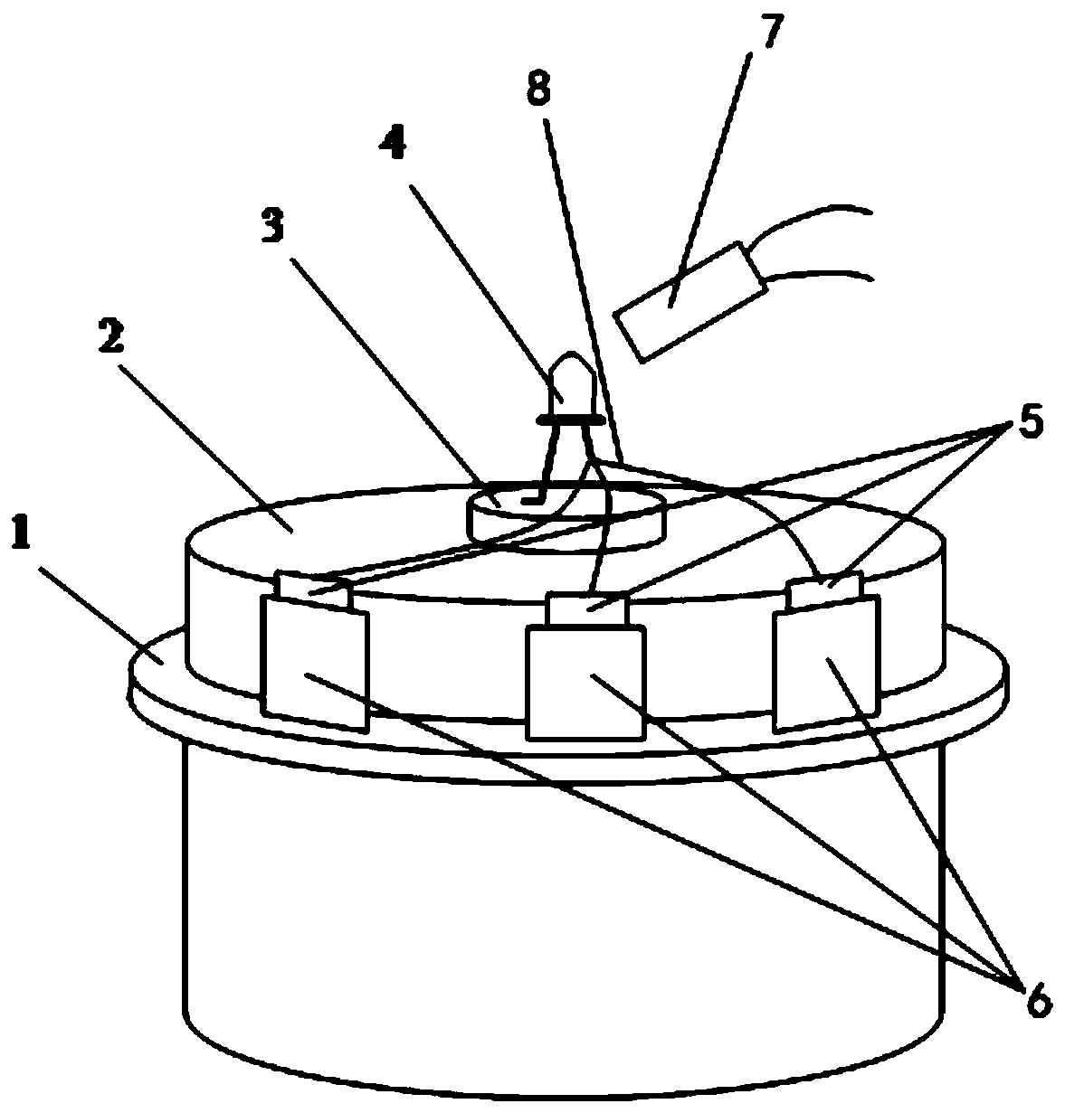
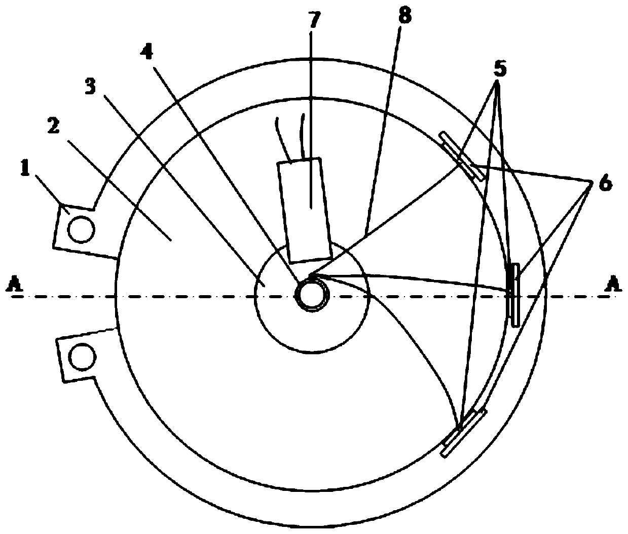
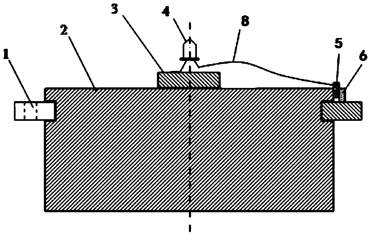
[0044] When using the Φ60mm shaft retaining ring 1, install the Φ60mm shaft retaining ring 1 on the shaft 2 with a diameter of 60mm, the diameter of the shaft groove is 57mm, and then install the monitoring device on the shaft 2 and the shaft retaining ring 1. When the rotation speed of the shaft 2 reaches 7920RPM, the light-emitting diode 4 goes out, and the output switching value of the photosensitive module 7 jumps from low level to high level, indicating that the contact state between the shaft retaining ring 1 and the shaft groove changes, and the shaft retaining ring 1 and the Looseness occurs between shaft grooves. Reduce the shaft rotation speed again, and the contact state between the s...


PUM


Abstract

The invention provides a monitoring device for a contact state between a shaft retaining ring and a shaft groove. The monitoring device comprises a battery; one pole of the battery is connected with apin of a light-emitting device; and the other pole is connected with a shaft electrically. The other pin of the light-emitting device is connected to a plurality of spaced conductive sheets by wires.The conductive sheets are in close contact with the peripheral surface of the shaft by lightweight insulating workpieces fixed on the shaft retaining ring. The light-emitting device faces a photosensitive sensor of a photosensitive module and the output of the photosensitive module is a switching quantity. According to the monitoring device provided by the invention, no high-precision gap sensoris needed and no mounting slot needs to be opened in the shaft of the sensor. Moreover, the monitoring device having a simple structure occupies small space and is convenient to load or unload. Real-time monitoring of the contact state between the shaft retaining ring and the shaft groove can be realized without affecting the operating state of the shaft retaining ring.

Description

technical field [0001] The invention relates to the technical field of contact state monitoring devices, in particular to a contact state monitoring device between a retaining ring for a shaft and a shaft groove. Background technique [0002] The retaining ring for shaft is a kind of fastener, which is fixed in the shaft groove through interference contact, and plays the role of fixing and sealing. It is widely used in the shafting mechanism of mechanical equipment. Replacing traditional fasteners with shaft retaining rings not only saves cost, but also facilitates installation and removal. China's industrial base strategy and "Made in China 2025" emphasize that core basic components are an important basis for enhancing the core competitiveness of the industry. As a basic component, the shaft retaining ring plays a vital role in the fields of transportation equipment, aerospace, wind power, etc., but it has been paid little attention. At present, domestic research on the s...

Claims


Application Information

Patent Timeline
Patent Type & Authority Patents(China)
IPC IPC(8): G01B7/14
CPCG01B7/144
Inventor 吴喆郑梦龙王升斌王纯贤叶军辉
Owner HEFEI UNIV OF TECH
Why Eureka
Try Eureka