
Quenching device capable of facilitating clamping and quenching of hardware materials

A technology of quenching device and clamping device, which is applied in the direction of quenching device, heat treatment equipment, furnace, etc., can solve the problems of workers being scalded, inability to uniformly quench hardware materials, inconvenient automatic clamping and fixing of hardware materials, etc., to achieve convenient quenching dead angle, Simplify the operation steps and avoid the effect of manual installation and clamping

Active Publication Date: 2019-01-01
YANCHENG NUOWEITE ELECTROMECHANICAL TECH
View PDF5 Cites 4 Cited by
  • Summary
  • Abstract
  • Description
  • Claims
  • Application Information

AI Technical Summary

Problems solved by technology

[0003] The purpose of the present invention is to provide a quenching device that is convenient for clamping and quenching hardware materials, so as to solve the problem that the existing quenching device proposed in the background technology is inconvenient to automatically clamp and fix cylindrical hardware materials, and the high-heat cylinder The fixed structure of the shaped hardware material is unstable, and it is easy to cause the material to slip off and cause burns to the workers, and it is impossible to fully and uniformly quench the hardware material

Method used


Image

  • Quenching device capable of facilitating clamping and quenching of hardware materials
  • Quenching device capable of facilitating clamping and quenching of hardware materials
  • Quenching device capable of facilitating clamping and quenching of hardware materials

Examples


Embodiment Construction

[0026] The following will clearly and completely describe the technical solutions in the embodiments of the present invention with reference to the accompanying drawings in the embodiments of the present invention. Obviously, the described embodiments are only some, not all, embodiments of the present invention. Based on the embodiments of the present invention, all other embodiments obtained by persons of ordinary skill in the art without making creative efforts belong to the protection scope of the present invention.

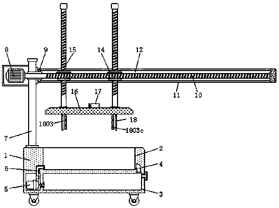
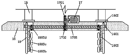
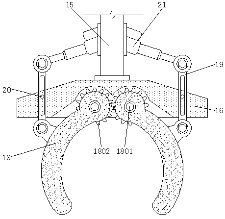
[0027] see Figure 1-7 , the present invention provides a technical solution: a quenching device that is convenient for clamping and quenching hardware materials, including a quenching box 1, a micro water pump 5, a mounting plate 7, a servo motor 8, a linkage rod 19 and a driving cylinder 21, and the quenching box 1 is provided with a quenching pool 2, and the bottom of the quenching pool 2 is provided with a liquid storage pool 3, and a connecting pipe 4 is ...


PUM


Abstract

The invention discloses a quenching device capable of facilitating clamping and quenching of hardware materials. The device comprises a quenching box, a micro water pump, a mounting plate, a servo motor, a linkage rod and a driving cylinder, wherein the quenching box is provided with a quenching bath, a connecting pipe is arranged at the right side of the quenching bath, and the quenching bath isconnected with a liquid storage tank by means of the connecting pipe; the micro water pump is connected with the left side of the liquid storage tank, and the liquid storage tank and the micro water pump are both positioned inside the quenching box; the linkage rod is positioned at the outer side a clamping device, and is connected with a mounting cover by means of a connecting rod; the linkage rod is connected with the driving cylinder, and the driving cylinder is positioned at the outer side of an adjusting rod. The quenching device capable of facilitating clamping and quenching of hardwarematerials facilitates the automatic clamping of the cylindrical hardware materials by using the clamping device, thus avoiding the high temperature damage to workers; a pushing device conveniently drives the hardware materials to rotate and roll in cooling liquid, so that the uniform quenching of the hardware materials is facilitated.

Description

technical field [0001] The invention relates to the technical field of hardware processing, in particular to a quenching device for conveniently clamping and quenching hardware materials. Background technique [0002] Hardware quenching processing is a heat treatment process for hardware metal materials. It is a heat treatment process that heats hardware materials to a critical temperature and then rapidly cools them at a lower cooling temperature. Traditional quenching processing usually requires workers to manually clamp high-heat hardware materials. Stretching into the quenching liquid for quenching will easily cause burns to the workers. At the same time, the surface of the cylindrical hardware material is smooth and the clamping is unstable. For example, the Chinese patent publication number is: a kind of hardware rod tool quenching device CN107841603A. This quenching device only The high-heat cylindrical hardware material is fixed by the upper and lower tops. The fixed...

Claims


Application Information

Patent Timeline
Patent Type & Authority Applications(China)
IPC IPC(8): C21D1/63C21D9/00
CPCC21D1/63C21D9/0018C21D9/0062
Inventor 吴玮
Owner YANCHENG NUOWEITE ELECTROMECHANICAL TECH
Learn More