Special lifting appliance for engine cylinder

A technology for engines and cylinders, which is applied in the field of special spreaders for engine cylinders, can solve problems such as insufficient safety, achieve the effect of not being easy to decouple and improve safety performance

Pending Publication Date: 2019-01-01
HUBEI UNIV OF TECH
View PDF5 Cites 1 Cited by
  • Summary
  • Abstract
  • Description
  • Claims
  • Application Information

AI Technical Summary

Problems solved by technology

[0005] The technical problem to be solved by the patent of this invention is to overcome the lack of safety of the existing engine cylinder special spreader and provide a safe and reliable engine cylinder special spreader

Method used


Image

  • Special lifting appliance for engine cylinder
  • Special lifting appliance for engine cylinder
  • Special lifting appliance for engine cylinder

Examples


Embodiment Construction

[0027] The present invention will be further described below in conjunction with the accompanying drawings and specific embodiments.

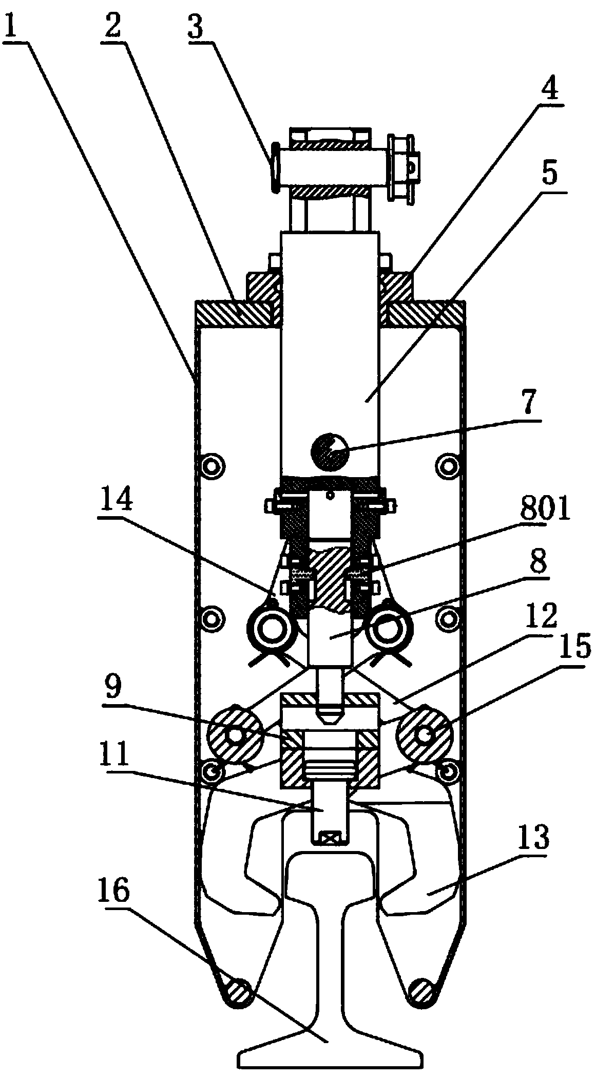
[0028] Such as figure 1 , 2 , Shown in 3,5, the outside of the present invention is casing, is made up of guide plate 6, casing side cover plate 1, casing upper cover plate 2. The upper part of the guide plate 6 is provided with a guide groove 601, and its bottom is designed with a V-shaped opening. Preferably, the included angle of the V-shaped opening is 45°.

[0029] Another example figure 1 , 2 , 3, the upper cover plate 2 of the box has a main shaft hole, the main shaft 5 is installed in the main shaft hole through the main shaft sleeve 4, the main body of the main shaft 5 extends into the inside of the box, and can The main shaft sleeve 4 is free to move. The upper part of the main shaft 5 is provided with an opening, and the guide shaft 7 is installed on the main shaft 5 through the opening. Both sides of the guide shaft 7 extend i...


PUM


Abstract

The invention relates to a special lifting appliance for an engine cylinder. The special lifting appliance comprises a box body, a main shaft, a main shaft sleeve, a reversing shaft with the lower endbeing provided with an inverted T-shaped armature, a guide plate, a positioning pin, a grab fixing shaft, a guide shaft, two pairs of connecting rods I, two pairs of connecting rods II, two pairs ofgrabs, a rising lug, a movable tongue and a positioning pin. The reversing shaft comprises a reversing shaft main body and a reversing shaft sleeve, the reversing shaft sleeve is provided with an upper circle and a lower circle of oblique teeth which alternatively correspond to each other, the upper circle and the lower circle of oblique teeth are respectively provided with four oblique teeth, andthe upper two adjacent oblique teeth or the lower two adjacent oblique teeth are separated from 90 degrees. The reversing shaft is installed inside the main shaft and can move up and down inside themain shaft, the positioning pin penetrates through the main shaft, and a head part of the positioning pin is inserted between the upper and lower oblique teeth of the reversing shaft sleeve. The two pairs of connecting rods II, the two pairs of connecting rods I and the two pairs of grabs form a multi-connecting-rod mechanism which is fixed on two sides of the main shaft by virtue of the guide shaft. A T-shaped through hole is arranged in the grab fixing shaft, and the movable tongue is arranged in the T-shaped through hole. The upper end of the grab fixing shaft is also provided with the rising lug, and a groove matched with the inverted T-shaped armature is arranged in the grab fixing shaft.

Description

technical field [0001] The invention relates to a special sling for engine cylinders, which belongs to the field of sling equipment for automobile manufacturers. Background technique [0002] At present, the hanger used by the car coupler in the automobile manufacturing factory to lift the automobile engine cylinder is mainly composed of a connecting pin, a suspension shaft, a transmission pin, a cam armature, a clamping block and a rotating shaft. The cam armature of this kind of automobile engine cylinder block spreader is square. When lifting, during the swinging process of the cylinder block, the clamping block is easy to squeeze the cam armature and move upward, and the rotating shaft is easy to bend and deform, which eventually leads to derailment accidents, that is, decoupling, which has a major impact on the safety of enterprise production. [0003] In addition, there is currently an engine cylinder hanger, which consists of a connecting pin, a hanging shaft, a posit...

Claims


Application Information

Patent Timeline
IPC IPC(8): B66C1/42
CPCB66C1/42
Inventor 朱清波宋庭新田家豪
Owner HUBEI UNIV OF TECH
Why Eureka
Try Eureka