Crow plate type hydraulic support loading device

A hydraulic support and plate type technology, applied in the field of frame transport vehicles, can solve the problems of long pulling and loading stroke, large swing of the support, difficult front-end hooking, etc., to achieve the effect of easy pulling, safe and stable loading process, and preventing chain decoupling.

Inactive Publication Date: 2016-08-10
长治市永华机械有限公司
View PDF0 Cites 0 Cited by
  • Summary
  • Abstract
  • Description
  • Claims
  • Application Information

AI Technical Summary

Problems solved by technology

[0002] The support needs to be realized by the frame transporter during the transfer process, and how to place the support on the frame transporter stably is a common problem. The problem existing in the lifting type transporter in the prior art is that the front-end hook Difficult, that is, when the bracket is on the car, the bracket needs to be lifted by the chain. This method often causes decoupling, and when hooking, it is necessary to manually enter the inside of the frame truck to connect the frame truck and the bracket through the chain. In this way There is a great potential safety hazard. In addition, when the bracket is lifted, due to the softness of the chain, the bracket swings greatly during the lifting process, and it often rubs and collides with the frame transporter, causing damage to the equipment.
[0003] Although the shovel-type racking method used in the prior art overcomes the instability of the hoisting-type racking method, it also brings the problems of long traction racking stroke and high friction

Method used


Image

  • Crow plate type hydraulic support loading device
  • Crow plate type hydraulic support loading device

Examples


Embodiment Construction

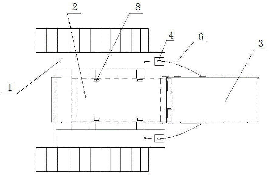
[0017] Such as figure 1 and figure 2 As shown, the skid plate type hydraulic support loading device of the present invention includes a U-shaped frame 1 and a support supporting plate 2, and the support supporting plate 2 is located between the two side walls of the U-shaped frame 1, and on the support supporting plate 2 The support 3 to be mounted on the car is set, and the upper surfaces of the two side walls of the U-shaped frame 1 are respectively provided with a traction cylinder 4, and the traction cylinder 4 is vertically arranged on the open end of the side wall of the U-shaped frame 1, and the traction cylinder 4 is vertically arranged on the open end of the side wall of the U-shaped frame 1. The movable end of the oil cylinder 4 is set upward, and the movable ends of the two traction cylinders 4 are respectively provided with a pulley 5, and the two pulleys 5 are respectively wound with a steel wire rope 6 for pulling the support 3, and one end of the steel wire rop...


PUM


Abstract

The skid plate type hydraulic support loading device of the present invention belongs to the field of frame transport vehicles; the technical problem to be solved is to provide a skid plate type hydraulic support loading device, and the steel wire rope is used instead of the original ring chain to pull the support, and the steel wire rope is easier to be connected with the vehicle. The bracket is fixed and not easy to decouple, and the traction position adopts the rear of the bracket base, so that the bracket enters the frame transport vehicle at the same time from the inclined angle to the horizontal angle; the technical solution adopted to solve this technical problem is: pry board type hydraulic support loading device, including Type frame and bracket supporting plate, the bracket supporting plate is located between the two side walls of the U-shaped frame, the bracket to be loaded is arranged on the bracket supporting plate, the traction oil cylinder is arranged on the side wall of the U-shaped frame, and the traction oil cylinder is vertically arranged on the U-shaped frame. On the side wall of the type frame, pulleys are arranged on the traction cylinder, and steel wire ropes for pulling the bracket are respectively wound on the pulleys. One end of the wire rope is fixed on the upper surface of the side wall of the U-shaped frame, and the other end of the wire rope is arranged on the bracket.

Description

technical field [0001] The invention relates to a skid-type hydraulic support loading device, which belongs to the technical field of frame transport vehicles. Background technique [0002] The support needs to be realized by the frame transporter during the transfer process, and how to place the support on the frame transporter stably is a common problem. The problem existing in the lifting type transporter in the prior art is that the front-end hook Difficult, that is, when the bracket is on the car, the bracket needs to be lifted by the chain. This method often causes decoupling, and when hooking, it is necessary to manually enter the inside of the frame truck to connect the frame truck and the bracket through a chain. Just there is very big potential safety hazard, and in addition, when support is hoisted, due to the softness of chain, support swings a lot during hoisting process, often rubs and collides with transporting frame car, causes the damage of equipment. [00...

Claims


Application Information

Patent Timeline
IPC IPC(8): E21F13/00
CPCE21F13/006
Inventor 常补孩常金风司天善周晓明王晓东马宵立黄小丽张志兵申和平
Owner 长治市永华机械有限公司
Why Eureka
Try Eureka