Work machine and rice planting machine

A working machine and engine technology, which is applied in the direction of machines/engines, agriculture, transplanting machinery, etc., can solve the problems of low maintainability, obstruction of shielding parts, etc., and achieve the effect of improving maintainability

Active Publication Date: 2018-12-21
YANMAR POWER TECHNOLOGY CO LTD
View PDF8 Cites 0 Cited by
  • Summary
  • Abstract
  • Description
  • Claims
  • Application Information

AI Technical Summary

Problems solved by technology

However, if the shielding member is attached to the shroud so as to surround the outer periphery of the radiator, the shielding member becomes an obstacle when performing maintenance work on the radiator, such as cooling water replenishment work, and there is a problem that the maintainability is low.

Method used


Image

  • Work machine and rice planting machine
  • Work machine and rice planting machine
  • Work machine and rice planting machine

Examples


Embodiment Construction

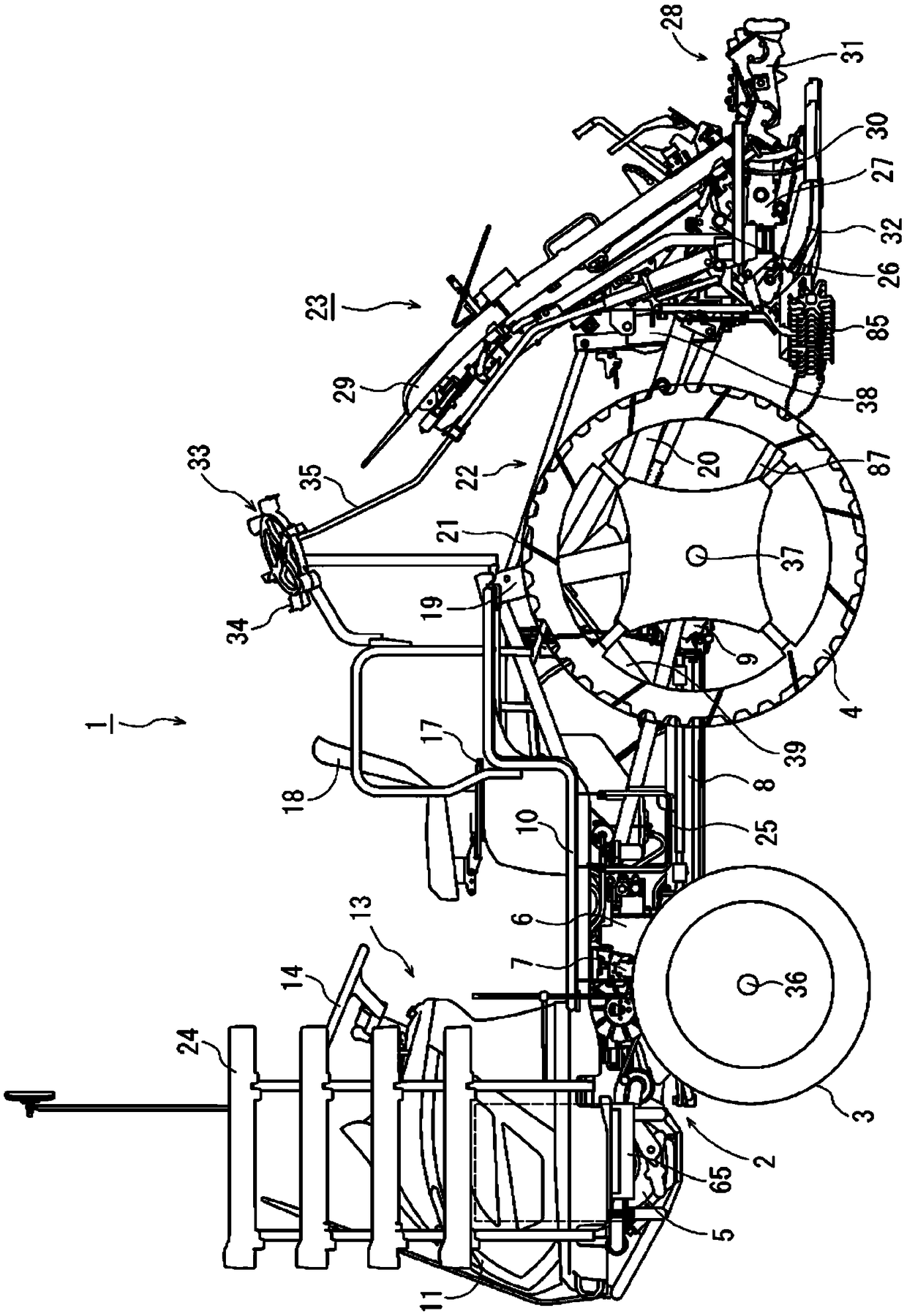
[0035] Hereinafter, it demonstrates based on drawing in the case of applying the embodiment which actualized this invention to the 8-row rice transplanting type riding-type rice transplanter 1 (it abbreviates as rice transplanter 1 hereafter) as a work machine. In addition, in the following description, the left side where the traveling direction of the traveling body 2 is located is simply referred to as the left side, and the right side where the traveling direction is located is simply referred to as the right side.

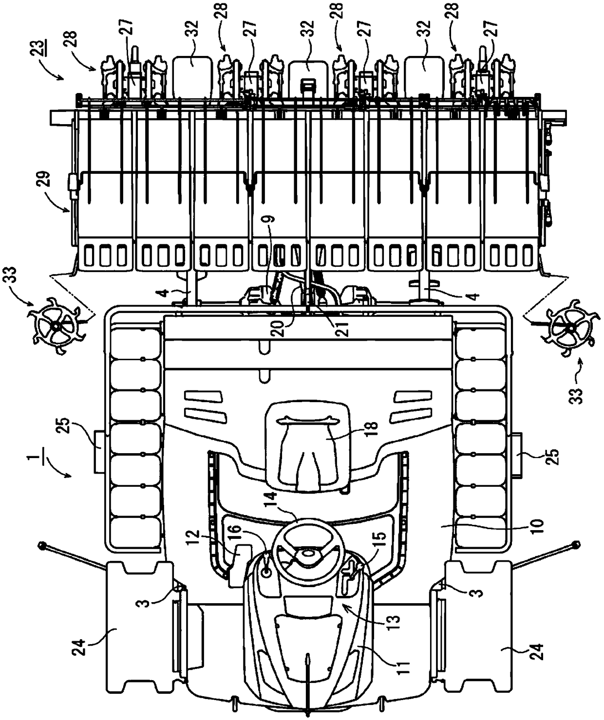
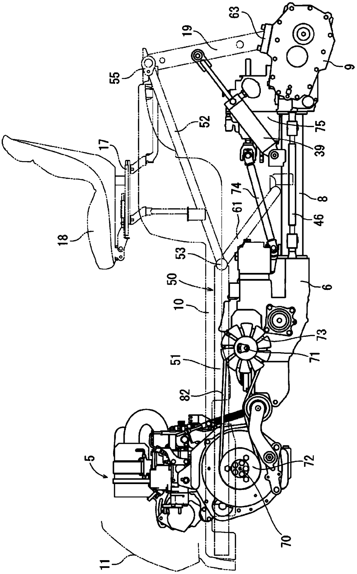
[0036] First, refer to figure 1 and figure 2 The outline|summary of the rice transplanter 1 is demonstrated. The rice transplanter 1 of embodiment has the traveling body 2 as a traveling part, and this traveling body 2 is supported by the left-right paired front wheel 3 and the left-right paired rear wheel 4 similarly. An engine 5 is mounted on the front portion of the traveling body 2 . By transmitting power from the engine 5 to the rear gearbox 6 to driv...


PUM


Abstract

A work machine 1 is provided with a travel chassis in which an engine is mounted, a bonnet 11 that covers the engine and that can open and close, a shroud 154 and radiator 153 disposed inside the bonnet 11 on the side of one-side part of the engine, and shielding members 146, 147 that close a gap between the shroud 154 and the bonnet 11. The first shielding member 146 is attached to the peripheralwall of the shroud 154 covering the outer periphery of the radiator 153, and is discontinuous above a feed-water spout 142 of the radiator 153. The second shielding member 147 is attached to a bonnet11a so as to join to the discontinuous part of the first shielding member 146 when the bonnet 11a is closed.

Description

technical field [0001] The present invention relates to a work machine and a rice transplanter. Background technique [0002] In a conventional work machine, a structure in which a cooling fan, a shroud, and a radiator are arranged sequentially from the engine side in an openable and closable engine hood surrounding an engine mounted on a traveling body (for example, refer to Patent Document 1 ). In the above configuration, if the warm air of the hood heated by the heat of the engine enters the suction side of the radiator through the gap between the hood and the hood, the cooling efficiency of the radiator and the engine decreases, so the hood and the hood The gap between the hoods is blocked by the shielding member. In the prior art disclosed in Patent Document 1, the upper end of the shroud extends upward, and a shielding member (trim) that contacts the inner surface of the hood is attached to the upper end of the shroud. [0003] patent documents [0004] Patent Docu...

Claims


Application Information

Patent Timeline
Patent Type & Authority Applications(China)
IPC IPC(8): B60K11/04A01C11/02B62D25/10F01P5/06
CPCA01C11/02B60K11/04B62D25/10F01P5/06B60Y2400/89
Inventor 绢田圭志
Owner YANMAR POWER TECHNOLOGY CO LTD
Why Eureka
Try Eureka