an inferior vena cava filter
A technology of vena cava and filter, applied in the field of medical equipment
- Summary
- Abstract
- Description
- Claims
- Application Information
AI Technical Summary
Problems solved by technology
Method used
Image

Examples
Embodiment 1
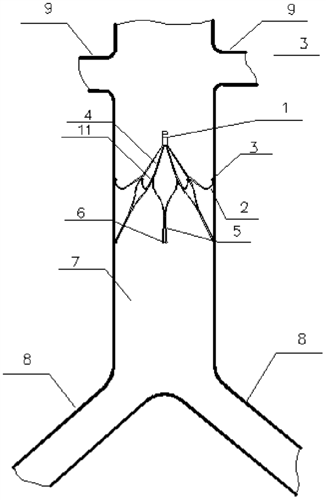
[0053] Such as figure 1 As shown, the vena cava filter involved in the present invention can be placed at the position of the inferior vena cava 7 between the renal vein 9 and the iliac vein 8 through an interventional method to prevent thrombus from the lower extremities from ascending into the lungs and causing pulmonary embolism. Such as figure 2 Or as shown in 4, we adopt a single-layer filter design, its structure has excellent mechanical stability, it is not easy to break and fall apart, and maintains its structural integrity. Recovery hook 1 is used for recovery of filter. Connecting part 12 is arranged on the below of recovery hook 1, and connecting part is provided with the part that is connected with pushing device inside, and the connection mode of connecting part and pushing device can be threaded connection, buckle connection and snare connection. The lower end of the connecting part 12 is divided into a plurality of first support rods 4 downwards, and each sup...
Embodiment 2
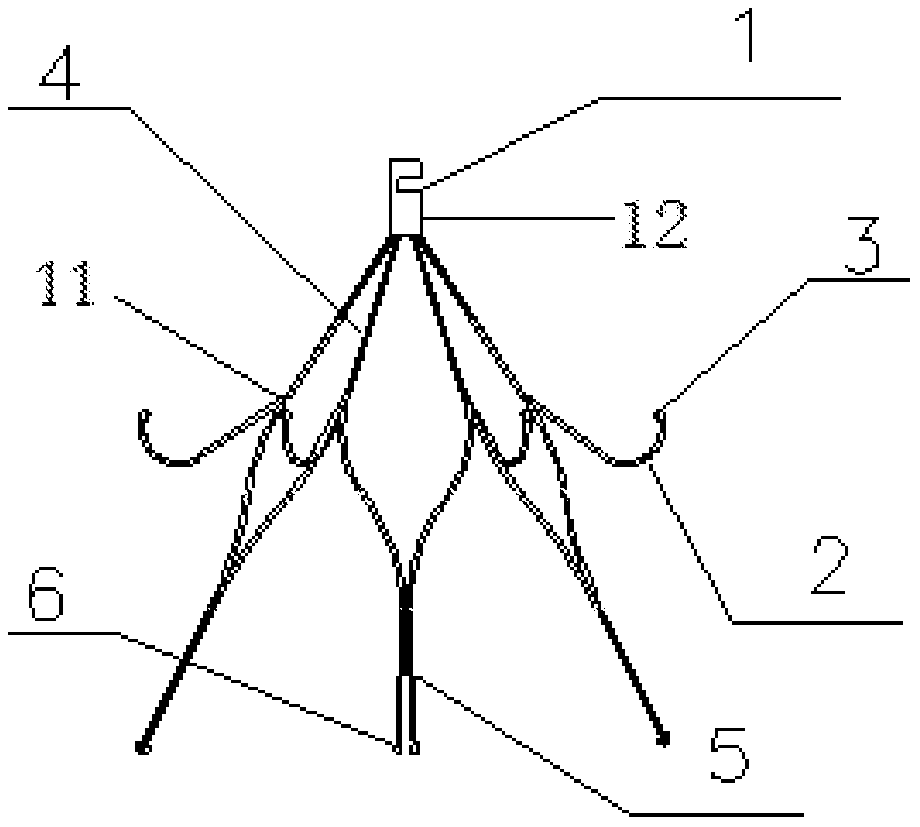
[0055] Such as figure 1 As shown, the vena cava filter involved in the present invention can be placed at the position of the inferior vena cava 7 between the renal vein 9 and the iliac vein 8 through an interventional method to prevent thrombus from the lower extremities from ascending into the lungs and causing pulmonary embolism. Such as figure 2 As shown, we adopt a single-layer filter design, which has excellent mechanical stability, is not easy to break and fall apart, and maintains its structural integrity. Such as figure 2 As shown, the vena cava filter of the present invention adopts a nickel-titanium alloy tube as a whole to be formed by laser cutting, and the nickel-titanium alloy tube used has antimagnetic properties and does not affect nuclear magnetic resonance imaging. Recovery hook 1 is used for recovery of filter. Connecting part 12 is arranged on the below of recovery hook 1, and connecting part is provided with the part that is connected with pushing de...
Embodiment 3
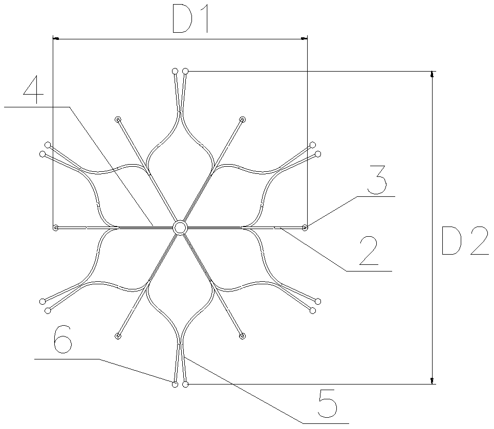
[0057] Such as figure 1 As shown, the vena cava filter involved in the present invention can be placed at the position of the inferior vena cava 7 between the renal vein 9 and the iliac vein 8 through an interventional method to prevent thrombus from the lower extremities from ascending into the lungs and causing pulmonary embolism. Such as Figure 4 As shown, we adopt a single-layer filter design, which has excellent mechanical stability, is not easy to break and fall apart, and maintains its structural integrity. Such as figure 2 As shown, the vena cava filter of the present invention adopts a nickel-titanium alloy tube as a whole to be formed by laser cutting, and the nickel-titanium alloy tube used has antimagnetic properties and does not affect nuclear magnetic resonance imaging. Recovery hook 1 is used for recovery of filter. Connecting part 12 is arranged on the below of recovery hook 1, and connecting part is provided with the part that is connected with pushing de...
PUM
 Abstract
Description
Claims
Application Information
 - R&D
- Intellectual Property
- Life Sciences
- Materials
- Tech Scout
- Unparalleled Data Quality
- Higher Quality Content
- 60% Fewer Hallucinations
Browse by: Latest US Patents, China's latest patents, Technical Efficacy Thesaurus, Application Domain, Technology Topic, Popular Technical Reports.
© 2025 PatSnap. All rights reserved.Legal|Privacy policy|Modern Slavery Act Transparency Statement|Sitemap|About US| Contact US: help@patsnap.com