
Pulse signal processing circuit and power supply circuit

A pulse signal and processing circuit technology, applied in the field of signal processing, can solve problems such as ineffective effects and poor versatility of filter circuits

Inactive Publication Date: 2018-12-21
坎德拉(深圳)科技创新有限公司
View PDF6 Cites 0 Cited by
  • Summary
  • Abstract
  • Description
  • Claims
  • Application Information

AI Technical Summary

Problems solved by technology

[0003] Based on this, it is necessary to propose a new pulse signal processing circuit and power supply circuit for the problems in the prior art that the effect of filtering the power supply by using capacitors and inductors is not obvious and the versatility of the filter circuit is poor.

Method used


Image

  • Pulse signal processing circuit and power supply circuit
  • Pulse signal processing circuit and power supply circuit
  • Pulse signal processing circuit and power supply circuit

Examples


Embodiment Construction

[0031] In order to facilitate the understanding of the present invention, the present invention will be described more fully below with reference to the associated drawings. A preferred embodiment of the invention is shown in the drawings. However, the present invention can be embodied in many different forms and is not limited to the embodiments described herein. Rather, these embodiments are provided so that the disclosure of the present invention will be thorough and complete.

[0032] Unless otherwise defined, all technical and scientific terms used herein have the same meaning as commonly understood by one of ordinary skill in the technical field of the invention. The terms used herein in the description of the present invention are for the purpose of describing specific embodiments only, and are not intended to limit the present invention. As used herein, the term "and / or" includes any and all combinations of one or more of the associated listed items.

[0033] It sho...


PUM


Abstract

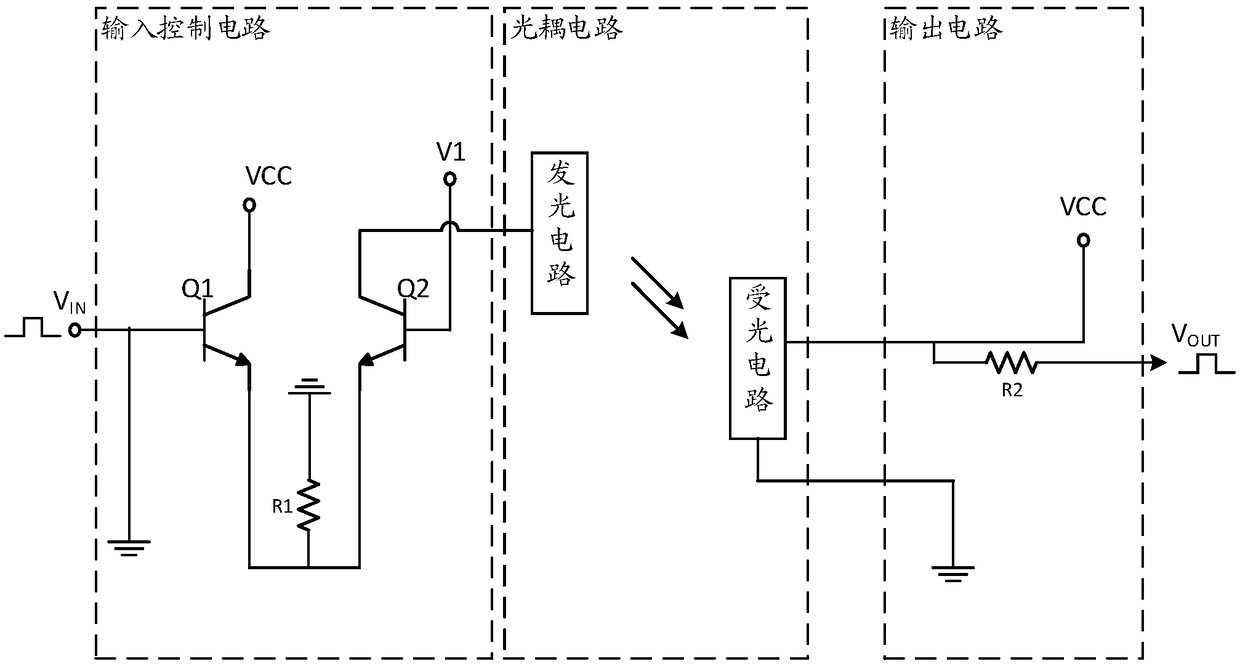
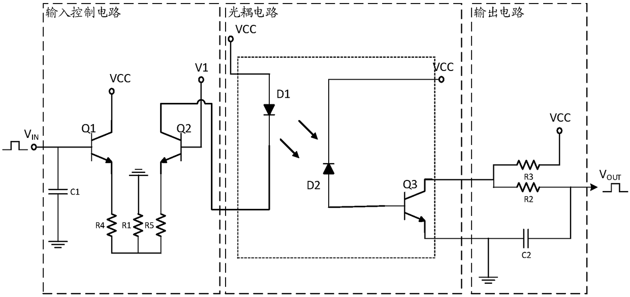
A pulse signal processing circuit includes an input control circuit, an optocoupler circuit and an output circuit, which are sequentially connected, wherein the input control circuit comprises a firstswitch tube,a second switch tube and a first resistor, the output terminals of the first switch tube and the second switch tube are grounded through the first resistor, the control terminal of the first switch tube is used as an input terminal for accessing the input pulse signal, the control terminal of the second switch tube is connected with a reference voltage, and the on-off of the optical coupling circuit is controlled by the on-off of the second switch tube; The output circuit includes a second resistor, one end of the second resistor serves as an output end of the output circuit, andthe other end of the second resistor is connected to both the second power supply unit and the optical coupling circuit and is grounded through the optical coupling circuit. By setting the reference voltage, the noise in the input pulse signal can be suppressed, so that the output of the circuit is not affected by the noise, so that the stable and noise-free pulse signal can be output.

Description

technical field [0001] The invention relates to the field of signal processing, in particular to a pulse signal processing circuit and a power supply circuit. Background technique [0002] In electronic equipment or electronic systems, there are usually unwanted signals other than useful signals, that is, noise, which will interfere with useful signals, and the final signal obtained after system processing is the superposition of useful signals and noise. Especially when there is an operational amplifier in the system, small noise will be amplified, affecting the accuracy of the signal, and even causing signal distortion, more glitches, and difficulty in identifying useful signals. Moreover, most power supplies will generate noise and ripple when they are connected to the system. Without noise reduction processing, it is difficult to obtain ideal output results. At present, capacitors and inductors are usually used for filtering, and capacitors or inductors with different p...

Claims


Application Information

Patent Timeline
IPC IPC(8): H03K3/57H03K3/013
CPCH03K3/013H03K3/57
Inventor 刘稻
Owner 坎德拉(深圳)科技创新有限公司
Learn More