
Micro power generation device

A power generation device and micro-power technology, applied in the direction of electromechanical devices, electrical components, electric components, etc., can solve the problems of high cost, difficult generator installation, large volume, etc., achieve stable output current and voltage, solve overexcitation phenomenon, volume small effect

Active Publication Date: 2018-12-21
罗中岭
View PDF10 Cites 1 Cited by
  • Summary
  • Abstract
  • Description
  • Claims
  • Application Information

AI Technical Summary

Problems solved by technology

[0002] Although there are many types of generators on the market, most of them are difficult to install, large in size, inconvenient to move, high in energy consumption, have great regional and limitations, and are expensive
The most important thing is that many generators on the market have over-excitation phenomenon when they output electric energy to the outside world. Over-excitation phenomenon will generate greater resistance, and if the generator works for a long time, it will continue to generate heat and cause excessive temperature, which will lead to burning , which greatly affects the normal operation and service life of the generator

Method used


Image

  • Micro power generation device
  • Micro power generation device
  • Micro power generation device

Examples


Embodiment Construction

[0034] The principles and features of the present invention are described below in conjunction with the accompanying drawings, and the examples given are only used to explain the present invention, and are not intended to limit the scope of the present invention.

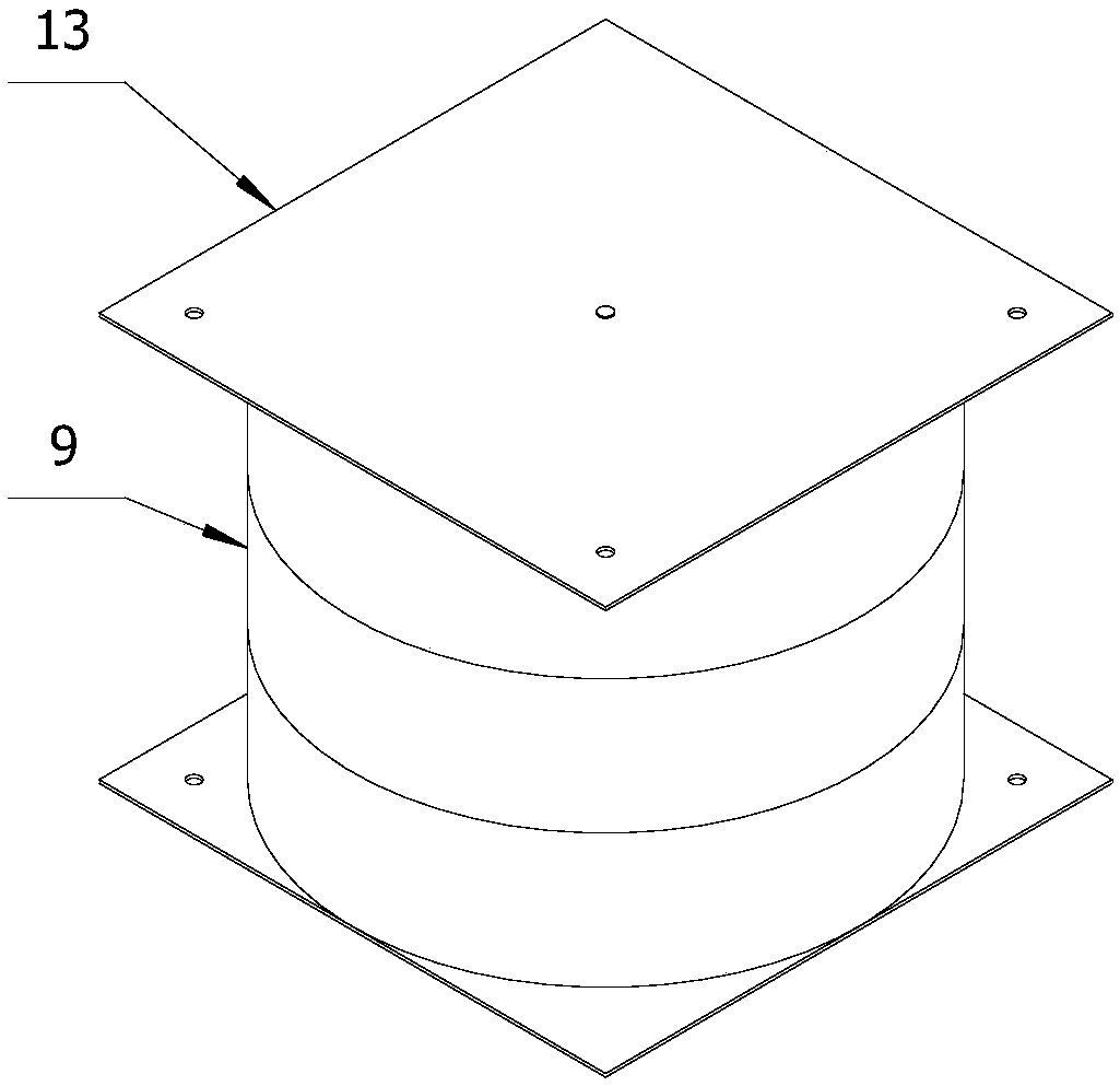
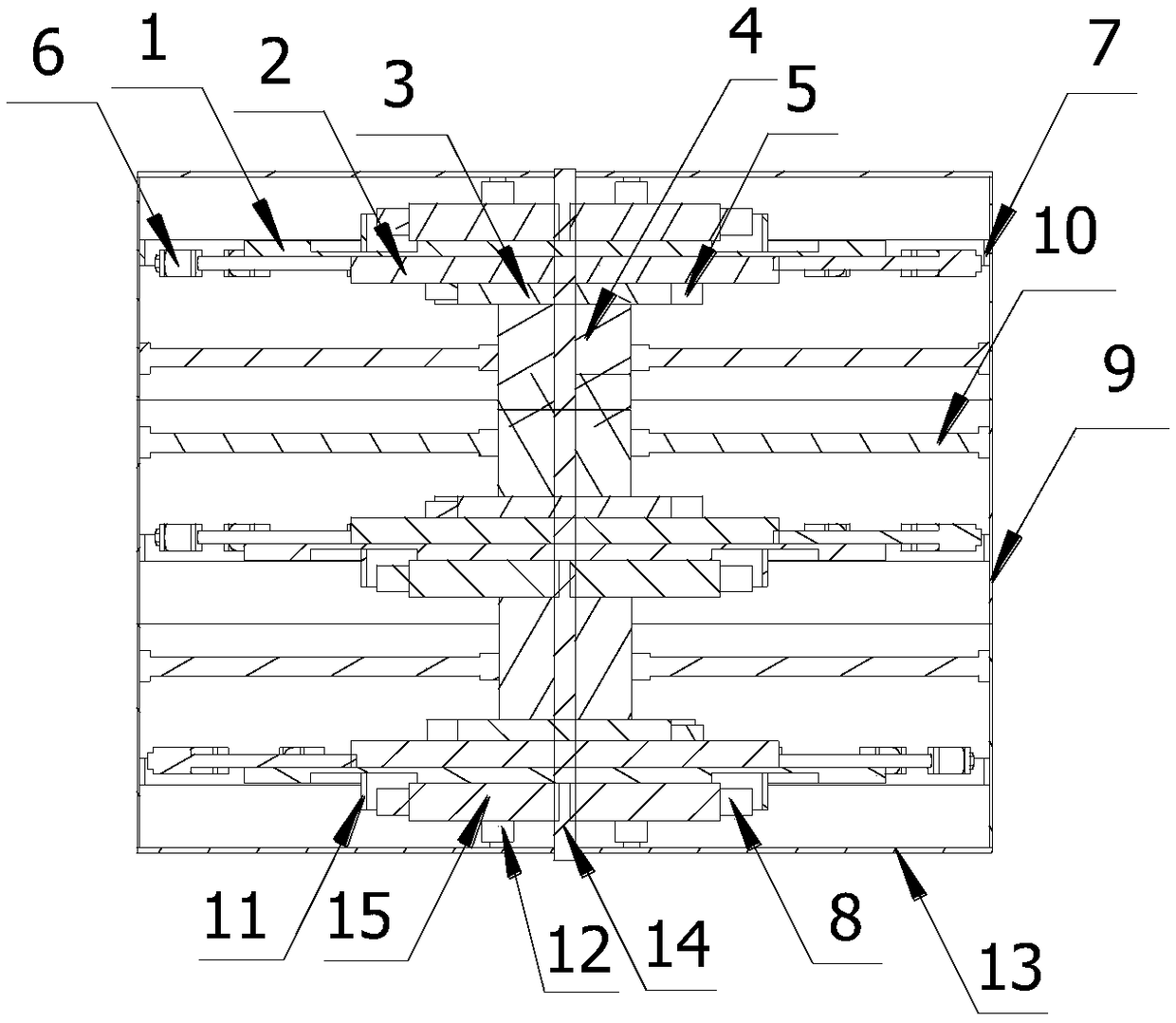
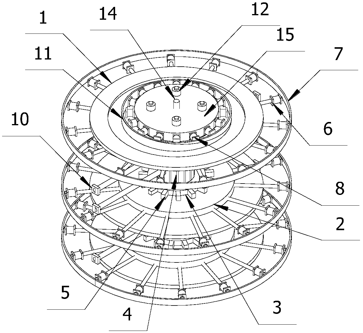
[0035] Such as figure 1 As shown, a micro power generating device includes two bases 13, a hollow and cylindrical casing 9, at least one power generation assembly arranged in the casing 9 and a central axis vertically arranged on the casing 9 The rotating shaft 14 on the top, the two bases 13 are respectively sealed and connected with the upper and lower ends of the casing 9, the power generation assembly includes a magnetic rotating assembly and an induction generating assembly, and the magnetic rotating assembly is arranged at one end of the rotating shaft 14 , and can rotate together with the rotating shaft 14, the induction power generation component is arranged at the center position of the corresponding motor ...


PUM


Abstract

A micropower generator includes two bases, a housing, a power generating assembly and a rotating shaft disposed within the housing, the two bases are respectively sealingly connected with the upper and lower ends of the shell, The power generation assembly comprises a magnetic rotating assembly and an induction power generation assembly. The magnetic rotating assembly is arranged at one end of therotating shaft and can rotate together with the rotating shaft. The induction power generation assembly is arranged at a center position of the corresponding motor assembly close to the correspondingbase side, and the induction power generation assembly is fixedly connected with the corresponding base inner wall. A micro power generation device according to the present invention, A magnetic rotate assembly is powered by an external power supply to form a rotating magnetic field, so that rotational torque is generated, The rotating shaft drives the whole magnetic rotating assembly to rotate relative to the induction power generation assembly, the induction power generation assembly generates induced current and outputs to the outside, and only a small starting current voltage can drive the magnetic rotating assembly to rotate, the whole device is small in volume and large in power, and the over-excitation phenomenon generated when the generator transmits energy externally is solved.

Description

technical field [0001] The invention relates to the technical field of power generation, in particular to a micro power generation device. Background technique [0002] Although there are many types of generators currently on the market, most of them are difficult to install, large in size, inconvenient to move, high in energy consumption, have great regional and limitations, and are expensive. The most important thing is that many generators on the market have over-excitation phenomenon when they output electric energy to the outside world. Over-excitation phenomenon will generate greater resistance, and if the generator works for a long time, it will continue to generate heat and cause excessive temperature, which will lead to burning , which greatly affects the normal operation and service life of the generator. Contents of the invention [0003] The technical problem to be solved by the present invention is to provide a micro power generating device for the above-ment...

Claims


Application Information

Patent Timeline
Patent Type & Authority Applications(China)
IPC IPC(8): H02K7/18H02K53/00
CPCH02K7/1807H02K53/00
Inventor 罗中岭
Owner 罗中岭
Learn More