
A transmission line protection device

A protection device and transmission line technology, applied in the direction of adjusting/maintaining mechanical tension, can solve problems such as normal operation of the power grid, hidden dangers of structural stability, short circuit of transmission lines, long transmission lines, etc., to improve the ability to resist deformation, installation and maintenance The effect of low cost and improved stability

Active Publication Date: 2020-06-30
STATE GRID JIANGSU ELECTRIC POWER CO LTD TAIZHOU POWER SUPPLY BRANCH +1
View PDF5 Cites 0 Cited by
  • Summary
  • Abstract
  • Description
  • Claims
  • Application Information

AI Technical Summary

Problems solved by technology

During the use of transmission lines, strong convective weather is often encountered, and the airflow will generate strong tension on long transmission cables. Since the transmission lines in the existing structure usually have a certain tensile deformation capacity, the instantaneous stress Under the action, the length of the transmission line may be blown and stretched. At the same time, the farther the distance between the poles, the greater the deformation of the transmission line between the poles. Due to the incomplete stress, pre-tightening force and deformation of each transmission line Similarly, the deformed transmission lines may be close to each other, resulting in short circuit, wire entanglement, etc., which will bring hidden dangers to the normal operation of the power grid and the stability of the structure.

Method used


Image

  • A transmission line protection device
  • A transmission line protection device
  • A transmission line protection device

Examples


Embodiment Construction

[0022] The invention will be described in detail below in conjunction with specific embodiments.

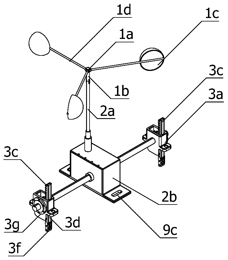
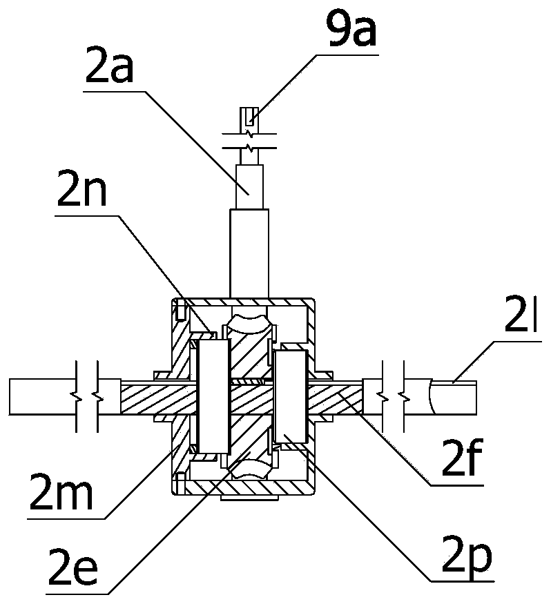
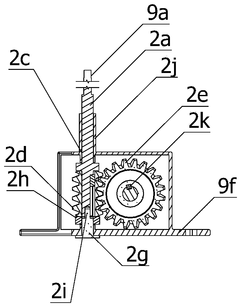
[0023] like figure 1 As shown, a transmission line protection device of the present invention includes a power assembly, a transmission assembly, and a plurality of adjustment assemblies; wherein the power assembly is used to obtain power from the wind by using a force-bearing bowl during use, and generates power according to the strength of the wind. Torques of different sizes, the torque is converted into the force of the rack 3c in the adjustment component on the transmission line 9e through the transmission component, and then produces different sizes of force on the transmission line 9e according to the wind strength, and an adaptive adjustment scheme is formed based on this principle .

[0024] like figure 1 , Figure 4 As shown in , the power assembly includes a hollow connection seat 1a, the lower end of the connection seat 1a is provided with a vertically downward pow...


PUM


Abstract

The invention belongs to the field of auxiliary equipment of distribution network, in particular to a transmission line protection device. A power unit is utilized to obtain the drive force and drivesthe rack down, so that the contact point of the transmission line and the adjusting assembly is moved downward, and the tensioning degree of the transmission line is improved, and the stronger the wind force is, the larger the downward moving distance of the gear is, and the higher the tensioning degree of the transmission line is, and the pretensioning force of the transmission line is enhancedwith the enhancement of the wind force, and the ability of the transmission line to resist deformation is improved after the pretensioning force is increased.

Description

technical field [0001] The invention belongs to the field of distribution network auxiliary equipment, in particular to a transmission line protection device. Background technique [0002] The power transmission line of the distribution network is now realized by erecting poles and connecting transmission lines between the poles to achieve power transmission. Because the transmission lines are heavy and contain high-voltage electricity, a large number of poles are required to support and suspend them. Usually The transmission line between the two poles needs to be tightened while applying a certain pre-tightening force but not too tight. On the one hand, it can prevent the structure from being damaged due to excessive stress. Expansion and contraction provide deformation allowance. During the use of transmission lines, strong convective weather is often encountered, and the airflow will generate strong tension on long transmission cables. Since the transmission lines in the...

Claims


Application Information

Patent Timeline
Patent Type & Authority Patents(China)
IPC IPC(8): H02G7/02
CPCH02G7/02
Inventor 季昆玉戴永东杨君中张勇张鹏
Owner STATE GRID JIANGSU ELECTRIC POWER CO LTD TAIZHOU POWER SUPPLY BRANCH
Learn More