A room floor heating pipeline design system

A technology for designing systems and floor heating pipes, applied in design optimization/simulation, calculation, instruments, etc., can solve problems such as inability to accurately understand the situation of floor heating pipes in rooms, unclear optimal path for floor heating layout and laying costs, etc. The effect of road design adjustment is convenient, easy to understand and easy to present

Active Publication Date: 2019-09-27
江苏橙智云信息技术有限公司
View PDF5 Cites 0 Cited by
  • Summary
  • Abstract
  • Description
  • Claims
  • Application Information

AI Technical Summary

Problems solved by technology

[0004] In view of the above technical problems, the present invention provides a room floor heating pipeline design system to solve the problems in the prior art that the situation of the room floor heating pipeline cannot be accurately understood, resulting in unclear optimal path of floor heating layout and laying costs.

Method used


Image

  • A room floor heating pipeline design system
  • A room floor heating pipeline design system
  • A room floor heating pipeline design system

Examples


Embodiment Construction

[0029] In order to facilitate the understanding of those skilled in the art, the present invention will be further described below in conjunction with the embodiments and accompanying drawings.

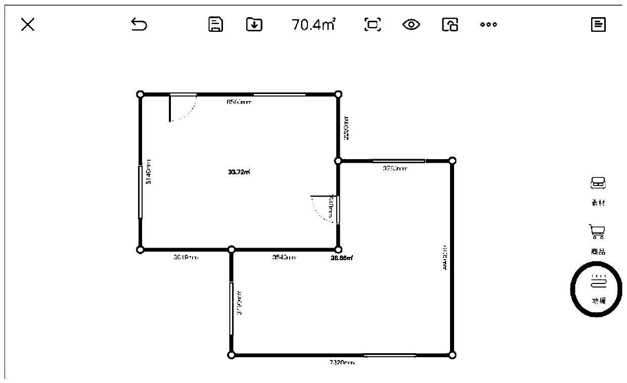
[0030] The floor heating pipeline design system of this embodiment includes a drawing module, a data acquisition module, and a data processing module. Such as Figure 4 The floor heating pipeline design flow chart shown in the drawing module draws the floor plan of the room to be installed with floor heating, obtains the room area, adds doors and windows and other facilities, and can also design other systems before editing the floor heating system, such as air conditioning systems, Fresh air system or water purification system, such as figure 1 shown. In the drawing of a 2D floor plan, if there is a door on the common edge of adjacent rooms, it is determined that the room areas are connected at the edge of the door; that is, the floor heating pipeline in one adjacent room can enter...


PUM


Abstract

The invention discloses a room floor heating pipeline design system, which comprises a drawing module for drawing the room area; a data acquisition module for acquiring spatial information of the roomarea, information on the construction area of ground heating, set floor heating pipe spacing; a data processing module: wherein according to the data of the data acquisition module, a ground heatingwiring loop is generated in the ground heating construction area. The system of the invention can intuitively and clearly show the design of the floor heating pipeline to the user, and improve the communication efficiency and the service quality before sale. At the same time, it is convenient to guide the construction work, reduce the construction errors caused by reading construction drawings, and improve the construction efficiency.

Description

technical field [0001] The invention belongs to the technical field of construction design in the heating and ventilating industry, and in particular relates to a room floor heating pipeline design system. Background technique [0002] The traditional floor heating pipeline layout is manually surveyed and drawn, and the pipeline is calculated. Before laying the pipeline, it is impossible to accurately and intuitively understand the pipeline layout. During the layout process, problems are prone to occur, resulting in wrong pipeline laying, uneven pipeline layout, and even Pipeline duplication, crossing, etc., the construction cost is high, and the construction period is generally longer due to the emergence of their own problems. Moreover, customers cannot clearly understand the cost of floor heating laying, and can only roughly calculate it based on the experience of construction personnel. [0003] At present, there is no intelligent tool for floor heating pipeline design,...

Claims


Application Information

Patent Timeline
Patent Type & Authority Patents(China)
IPC IPC(8): G06F17/50
CPCG06F30/13G06F30/20
Inventor 付杰李晓明
Owner 江苏橙智云信息技术有限公司
Why Eureka
Try Eureka