
Motor for compressor

A technology for compressors and motors, which is applied in the field of compressors and can solve problems such as danger, poor control of system return air overheating, and high exhaust temperature

Active Publication Date: 2018-12-21
QUANZHOU HUADE ELECTROMECHANICAL EQUIP
View PDF6 Cites 0 Cited by
  • Summary
  • Abstract
  • Description
  • Claims
  • Application Information

AI Technical Summary

Problems solved by technology

[0002] The working circuit of the air conditioner compressor is divided into evaporation area (low pressure area) and condensation area (high pressure area). The indoor unit and outdoor unit of the air conditioner belong to the low pressure or high pressure area respectively (depending on the working status). In the outdoor unit, the air conditioner compressor extracts the refrigerant from the low-pressure area, compresses it, and then sends it to the high-pressure area for cooling and condensation. The heat is released into the air through the heat sink, and the refrigerant changes from gaseous to liquid, and the pressure increases. Then it flows from the high-pressure area to the low-pressure area, and is sprayed into the evaporator through the capillary tube. The pressure drops suddenly, and the liquid refrigerant immediately turns into a gaseous state, and absorbs a large amount of heat in the air through the cooling fins. The heat at one end of the low-pressure area is absorbed into the refrigerant and then sent to the high-pressure area to be dissipated into the air, which plays a role in regulating the temperature. The motor cooling is not good, the system returns air overheating control is poor, the return air temperature is too high or the return air volume is low, Insufficient cooling of the motor, which often occurs in air-cooled heat pump units, and excessively high return air temperature will also lead to excessively high exhaust temperature, causing a series of problems. Therefore, compressor manufacturers will propose some use restrictions and take measures Some protective measures, such as liquid injection cooling, etc., prevent it from happening, and the equipment will vibrate and the temperature will not be controlled, which will easily lead to its safety and operating effect.
[0003] For the current compressor motor, it is easy to generate vibration due to its fast running speed. The vibration has a huge image on its internal equipment and operation, and it is likely to cause unnecessary danger. The process of its internal flow rate is caused by The generated temperature will affect the temperature of the internal equipment, and its operation effect will be affected when the internal temperature of the equipment changes greatly.

Method used


Image

  • Motor for compressor
  • Motor for compressor
  • Motor for compressor

Examples


Embodiment

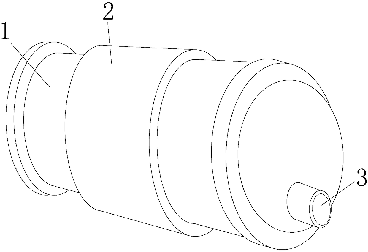
[0024] see Figure 1-Figure 4 , the present invention provides a motor for a compressor, the structure of which includes a compressor operating box 1, a protective fixing sleeve 2, and a connection port 3;

[0025] The outer surface of the compressor running box 1 is nested with the protective fixing sleeve 2 and is located on the same axis, and the connecting port 3 is embedded in one end of the side of the compressor running box 1 and connected to each other;

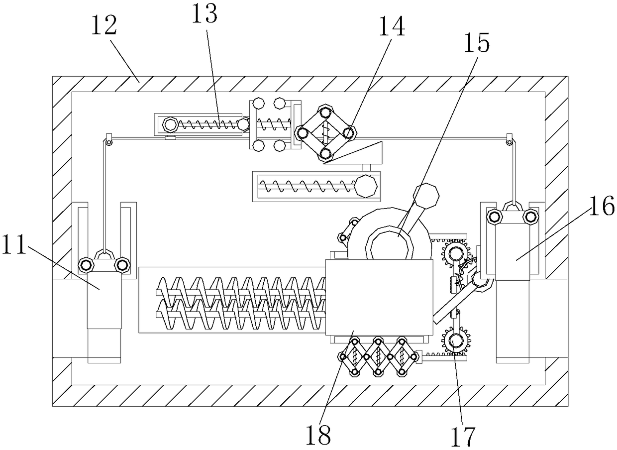
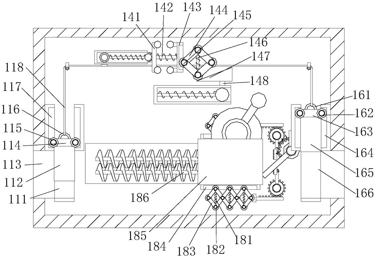
[0026] The compressor running box 1 includes a speed control outlet port 11, a protective shell 12, a pulling control rope device 13, a connection pushing device 14, a rotating magnetic field wheel 15, a pressure limiting access port 16, a stabilizing device 17, and a shaking induction group 18 ;

[0027] The speed control outlet 11 is embedded inside the side of the protective shell 12, the pressure limiting access port 16 is installed inside the protective shell 12 at the end away from the speed control outlet 11, ...


PUM


Abstract

The invention discloses a motor for a compressor. The motor for the compressor comprises a compressor operation box, a protective fixed sleeve and a joint port; the outer surface of the compressor operation box and the protective fixed sleeve are engaged and positioned in the same axis; the compressor operation box comprises a speed control outlet end, a protective shell, a pull rope control device, joint pushing equipment, a rotating magnetic field wheel, a pressure limiting access port, stabilizing devices and a shaking induction set; the speed control outlet end is embedded in the side of the protective shell; one end of the pull rope control device is movably connected with the joint pushing equipment; the stabilizing devices are mounted on the upper and lower sides of the shaking induction set, and are symmetrically distributed; and the rotating magnetic field wheel is arranged on the back upper side of the shaking induction set. Based on the prior art, internal equipment can be touched when the flowing speed is higher and the flowing pressure is higher, so that the sizes of two ports are needed to adjust for recovery; and when the vibration is generated, the external equipment is induced and timely fixed.

Description

technical field [0001] The invention relates to the field of compressors, in particular to a motor for a compressor. Background technique [0002] The working circuit of the air conditioner compressor is divided into evaporation area (low pressure area) and condensation area (high pressure area). The indoor unit and outdoor unit of the air conditioner belong to the low pressure or high pressure area respectively (depending on the working status). In the outdoor unit, the air conditioner compressor extracts the refrigerant from the low-pressure area, compresses it, and then sends it to the high-pressure area for cooling and condensation. The heat is released into the air through the heat sink, and the refrigerant changes from gaseous to liquid, and the pressure increases. Then it flows from the high-pressure area to the low-pressure area, and is sprayed into the evaporator through the capillary tube. The pressure drops suddenly, and the liquid refrigerant immediately turns in...

Claims


Application Information

Patent Timeline
Patent Type & Authority Applications(China)
IPC IPC(8): F04B35/04F04B49/00H02K5/24
CPCF04B35/04F04B49/00H02K5/24
Inventor 蒙建敏
Owner QUANZHOU HUADE ELECTROMECHANICAL EQUIP
Learn More