An automatic conveying frame for electric construction

A technology of automatic transportation and electric power construction, applied in the direction of conveyors, mechanical conveyors, conveyor objects, etc., can solve the problems of increased workload, physical exertion, and increased construction costs of power infrastructure, so as to reduce construction costs and avoid work The effect of volume increase

Active Publication Date: 2020-03-31
SHANDONG DESHENG ELECTRIC POWER CO LTD
View PDF12 Cites 0 Cited by
  • Summary
  • Abstract
  • Description
  • Claims
  • Application Information

AI Technical Summary

Problems solved by technology

[0002] With the strong demand for power, the demand for power infrastructure has been further promoted. In the process of power infrastructure construction, power towers, power meters, power cabinets, and distribution stations are one of the common basic equipment. In the process of installing power infrastructure equipment in mountainous areas, because it is located in the hillside area, the distribution station can only be installed and fixed on the hillside area, and in the process of installing power towers, meter boxes and power cabinets due to the large number and Among them, most of the transportation of power equipment is done by manpower. Due to the installation of power towers, power meters and power cabinets, there are many parts, so it takes many times and a long time to go back and forth to pick up parts. As a result, the workload increases, and because it is located on a hillside, it further causes physical exertion and further increases the cost of power infrastructure construction

Method used


Image

  • An automatic conveying frame for electric construction
  • An automatic conveying frame for electric construction
  • An automatic conveying frame for electric construction

Examples


Embodiment Construction

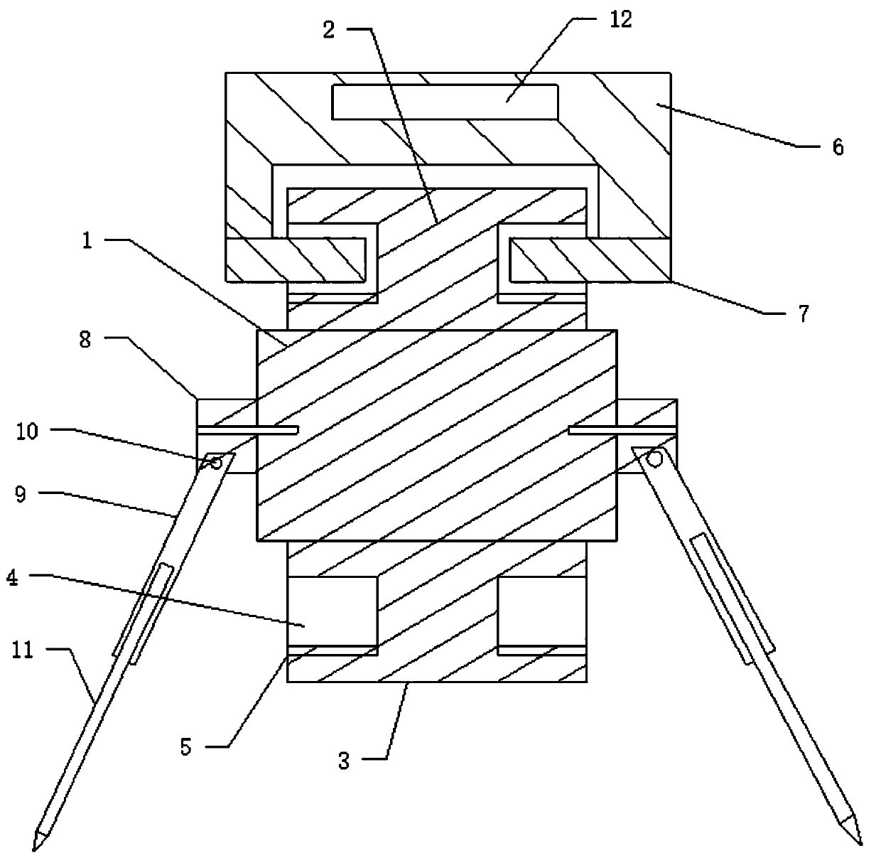
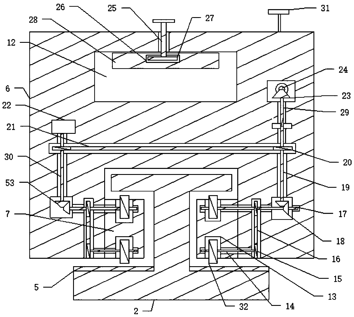
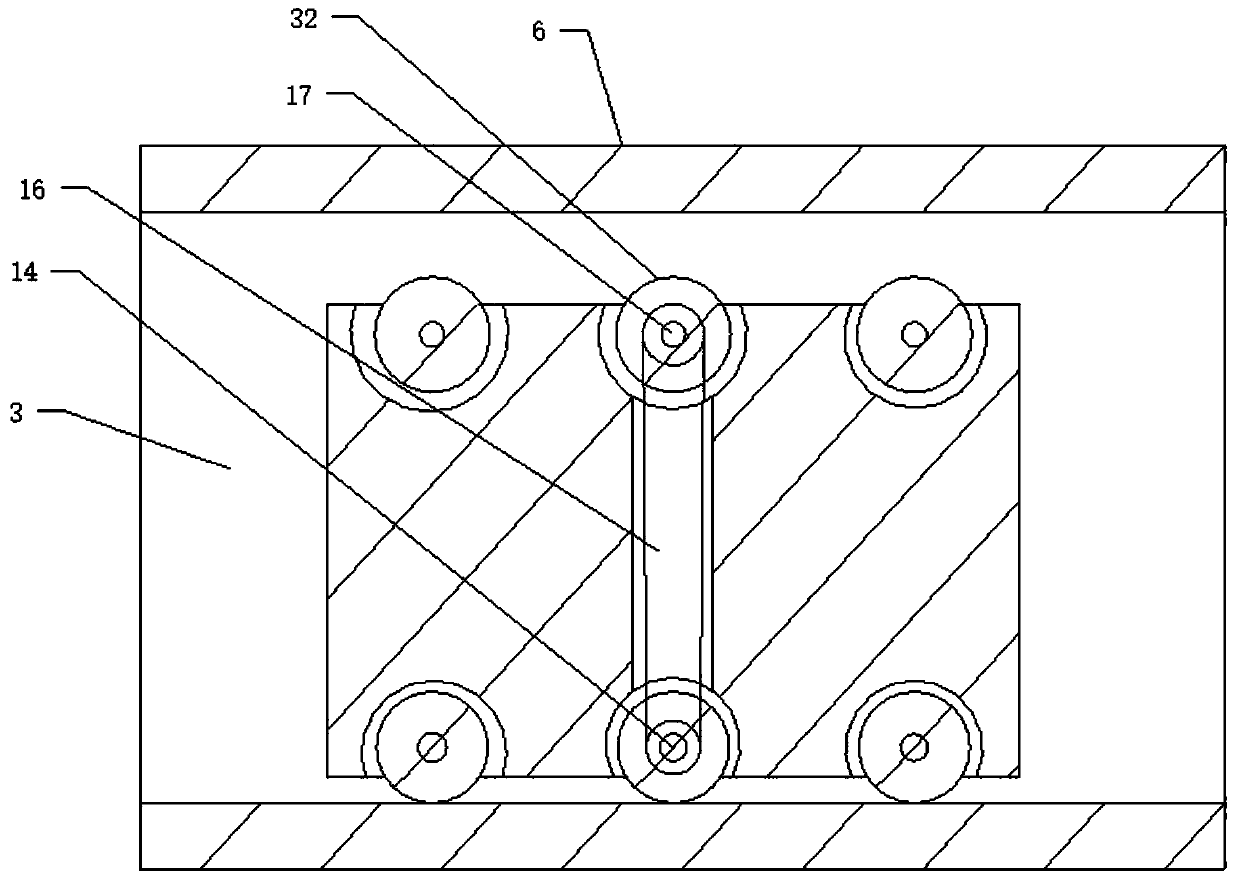
[0028] Such as Figure 1 to Figure 8 As shown, an automatic electric power construction conveyor frame includes a plurality of support bodies 1 connected side by side, and first support rods 9 supporting the support body 1 are respectively arranged on both sides of the support body 1, and the support body 1 The upper and lower sides are respectively connected with a first slideway 2 and a second slideway 3, and the two sides of the first slideway 2 and the second slideway 3 are respectively provided with a support slideway 4, and the support An engaging rack 5 is respectively arranged in the chute 4, and a sliding sliding conveying body 6 is respectively arranged on the first slideway 2 and the second slideway 3, and the two sides of the sliding conveying body 6 are respectively arranged There is a support slider 5 sliding in the support chute 4, the two sides of the support slider 5 are respectively provided with rotating meshing gears 32, and the meshing gears 32 correspond ...


PUM


Abstract

The invention discloses an electric power construction automatic conveying frame. The automatic conveying frame comprises a plurality of supporting bodies which are connected side by side, a first slide way and a second slide way are correspondingly connected to the upper side and the lower side of each supporting body, the two sides of the first slide ways and the two sides of the second slide ways are correspondingly provided with supporting slide grooves, meshing racks are arranged in the supporting sliding groove correspondingly, sliding conveying bodies are arranged slidably on the firstslide ways and the second slide ways correspondingly, the two sides of the sliding conveying bodies are each provided with a supporting sliding block which slides in the corresponding supporting sliding groove, and the two sides of the supporting sliding blocks are correspondingly provided with rotating meshing gears. According to the automatic conveying frame, the meshing gears rotate so as to drive the sliding conveying bodies to slide, electric power equipment can be conveyed, increase of workloads caused by manually carrying equipment can be avoided, and construction cost of electric powerinfrastructure can be reduced.

Description

technical field [0001] The invention relates to electric power construction equipment, in particular to an automatic electric power construction conveying frame, in particular to an electric power construction automatic conveying frame capable of automatically conveying components in the electric power construction process. Background technique [0002] With the strong demand for power, the demand for power infrastructure has been further promoted. In the process of power infrastructure construction, power towers, power meters, power cabinets, and distribution stations are one of the common basic equipment. In the process of installing power infrastructure equipment in mountainous areas, because it is located in the hillside area, the distribution station can only be installed and fixed on the hillside area, and in the process of installing power towers, meter boxes and power cabinets due to the large number and Among them, most of the transportation of power equipment is do...

Claims


Application Information

Patent Timeline
Patent Type & Authority Patents(China)
IPC IPC(8): B65G47/74
CPCB65G35/00
Inventor 不公告发明人
Owner SHANDONG DESHENG ELECTRIC POWER CO LTD
Why Eureka
Try Eureka