
A control method for an intelligent low-temperature smoke chamber heating control system

A heating control and control method technology, applied in the field of electronic cigarettes, can solve the problems of wasting shredded tobacco, unable to make full use of shredded tobacco, etc., and achieve the effect of easy shape

Active Publication Date: 2020-09-04
芜湖启迪睿视信息技术有限公司
View PDF7 Cites 0 Cited by
  • Summary
  • Abstract
  • Description
  • Claims
  • Application Information

AI Technical Summary

Problems solved by technology

[0004] The purpose of the present invention is to provide a control method for an intelligent low-temperature tobacco cavity heating control system to solve the problem that in the prior art, due to the use of a fixed constant temperature heating method, the amount of smoke generated by the smoke column cannot be controlled according to user needs, and the shredded tobacco cannot be fully utilized to waste shredded tobacco and electric energy Defects

Method used


Image

  • A control method for an intelligent low-temperature smoke chamber heating control system
  • A control method for an intelligent low-temperature smoke chamber heating control system
  • A control method for an intelligent low-temperature smoke chamber heating control system

Examples


Embodiment 1

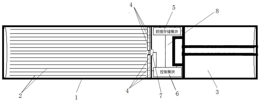
[0034] In this embodiment, the heating resistors 4 are fan-shaped plates arranged in a circle along the circumference of the smoke chamber 1 and installed at the bottom of the smoke chamber 1 . Compared with Embodiment 1, the number of heating resistors 4 is less, and the shape is easy to assemble, but the corresponding control of the heating speed is relatively rough, because more heating needles 2 have been set on a fan-shaped heating resistor 4 .

Embodiment 2

[0036]In this embodiment, the heating resistors 4 are strip-shaped plates, which are arranged in several layers in a ring around the center of the smoke chamber 1 and installed at the bottom of the smoke chamber 1 . Compared with Example 1, the heating resistor 4 of the strip plate is used, and the number of heating resistors 4 required by the smoke chamber 1 of the same cross section is larger, but it can also be controlled more carefully for heating speed, and can further reduce the consumption of shredded tobacco and electric energy. waste.

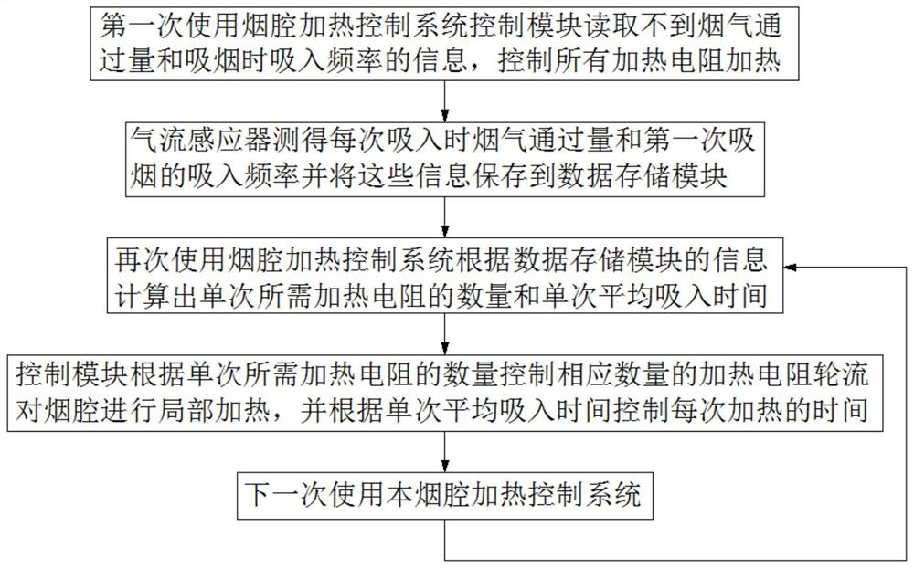
[0037] S1. Turn on the switch for the first time to use the smoke cavity heating control system. The control module 6 cannot read the information of the smoke throughput and the inhalation frequency when smoking, and controls the heating of all the heating resistors 4;

[0038] S2. The air flow sensor 7 detects the smoke throughput when smoking each time and sends the information generated to the control module 6. The control module 6 ...


PUM


Abstract

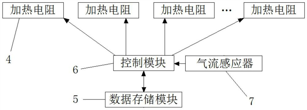
The invention discloses a control method for an intelligent low-temperature smoke chamber heating control system. The smoke chamber heating control system includes a heating needle, a heating resistor, a temperature sensor, an airflow sensor, a data storage module, a control module and a battery. The heating acupuncture Enter the smoke chamber filled with tobacco. There are several heating resistors. Each heating resistor is connected to several heating needles. The airflow sensor is located at the suction port at the bottom of the smoke chamber. The control module is electrically connected to each heating resistor. The airflow sensor The sensor signal is connected to the control module, and the data storage module signal is connected to the control module. The control module reads the inhalation frequency during previous use, the amount of smoke generated by a unit heating resistor and the amount of smoke passed through several inhalations, and calculates the number of heating resistors required for a single time and the average inhalation time of a single time. The invention The heating area and heating time are controlled by each heating resistor. In this way, the heating speed of the cut tobacco can be controlled according to the smoker's habits, thereby avoiding the failure to fully utilize the cut tobacco and wasting the cut tobacco and electric energy.

Description

technical field [0001] The invention relates to the field of electronic cigarettes, in particular to a control method for an intelligent low-temperature cigarette cavity heating control system. Background technique [0002] The heating method of traditional cigarettes is to ignite and heat. Not only will there be an open flame when ignited, but also some harmful and carcinogenic substances will be produced when burned in the air. As the flow of smoke is released into the environment, it will have a certain impact on the environment. . [0003] The nicotine in tobacco leaves is not only released by ignition. In recent years, non-combustion heating cigarette devices have appeared, which can heat or even carbonize shredded tobacco without igniting it, and reach a certain temperature to make the nicotine ingredients volatilize for people to smoke. suck. Electric heating is often used. For example, the utility model patent with the application number of 201520621609.0 provides...

Claims


Application Information

Patent Timeline
Patent Type & Authority Patents(China)
IPC IPC(8): A24F40/46A24F40/40
CPCA24F40/20A24F40/40A24F40/50A24F40/51A24F40/57A24F40/42A24F40/46
Inventor 盛焱新
Owner 芜湖启迪睿视信息技术有限公司
Learn More