A rotor core and an electric machine having the same

A rotor core and rotor body technology, applied in the direction of synchronous machines, electric components, electrical components, etc., can solve the problems that the main magnetic flux cannot be adjusted according to needs, the operating range of the motor is narrow, and the speed regulation range is limited, so as to reduce the Effects of vibration and noise, reduced field weakening requirements, and increased adjustable range

Pending Publication Date: 2018-12-18
ZHUHAI GREE REFRIGERATION TECH CENT OF ENERGY SAVING & ENVIRONMENTAL PROTECTION
View PDF0 Cites 4 Cited by
  • Summary
  • Abstract
  • Description
  • Claims
  • Application Information

AI Technical Summary

Problems solved by technology

[0002] With the advancement of technology, permanent magnet synchronous motors are used more and more in manufacturing due to their own advantages; the existing permanent magnet motors are fixed due to the permanent magnet magnetomotive force, the main magnetic flux cannot be adjusted according to needs, and the operating range of the motor is narrow. The speed range is limited, and the magnetic flux obtained at low speed is small

Method used


Image

  • A rotor core and an electric machine having the same
  • A rotor core and an electric machine having the same
  • A rotor core and an electric machine having the same

Examples


Embodiment 1

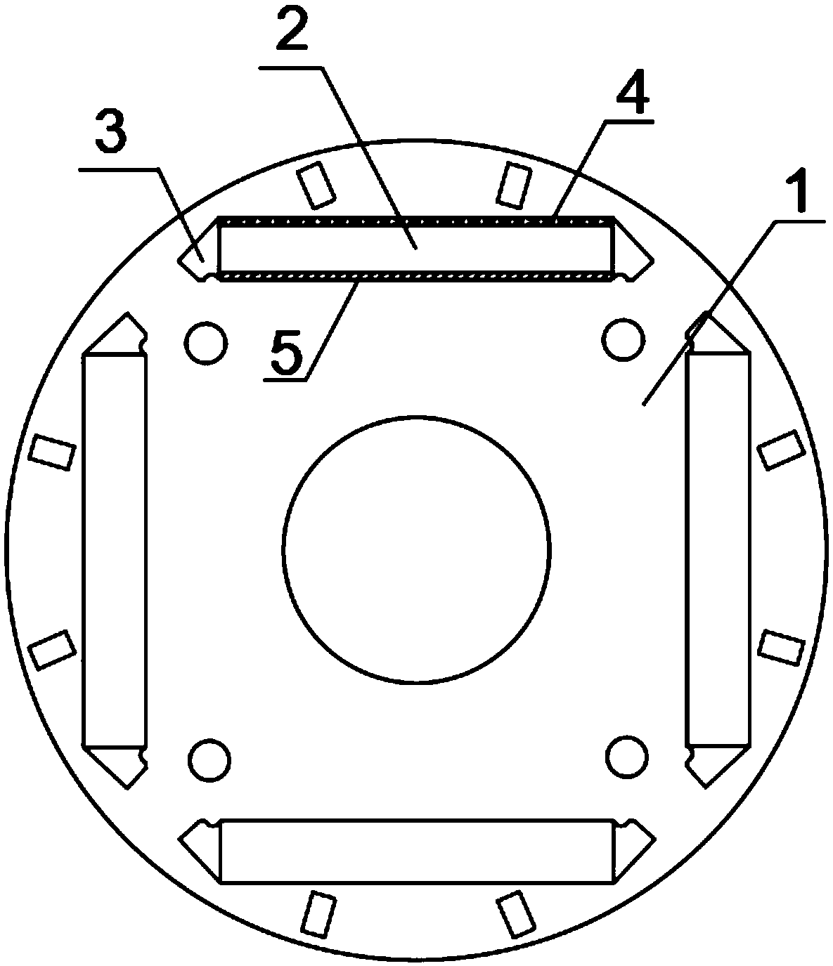
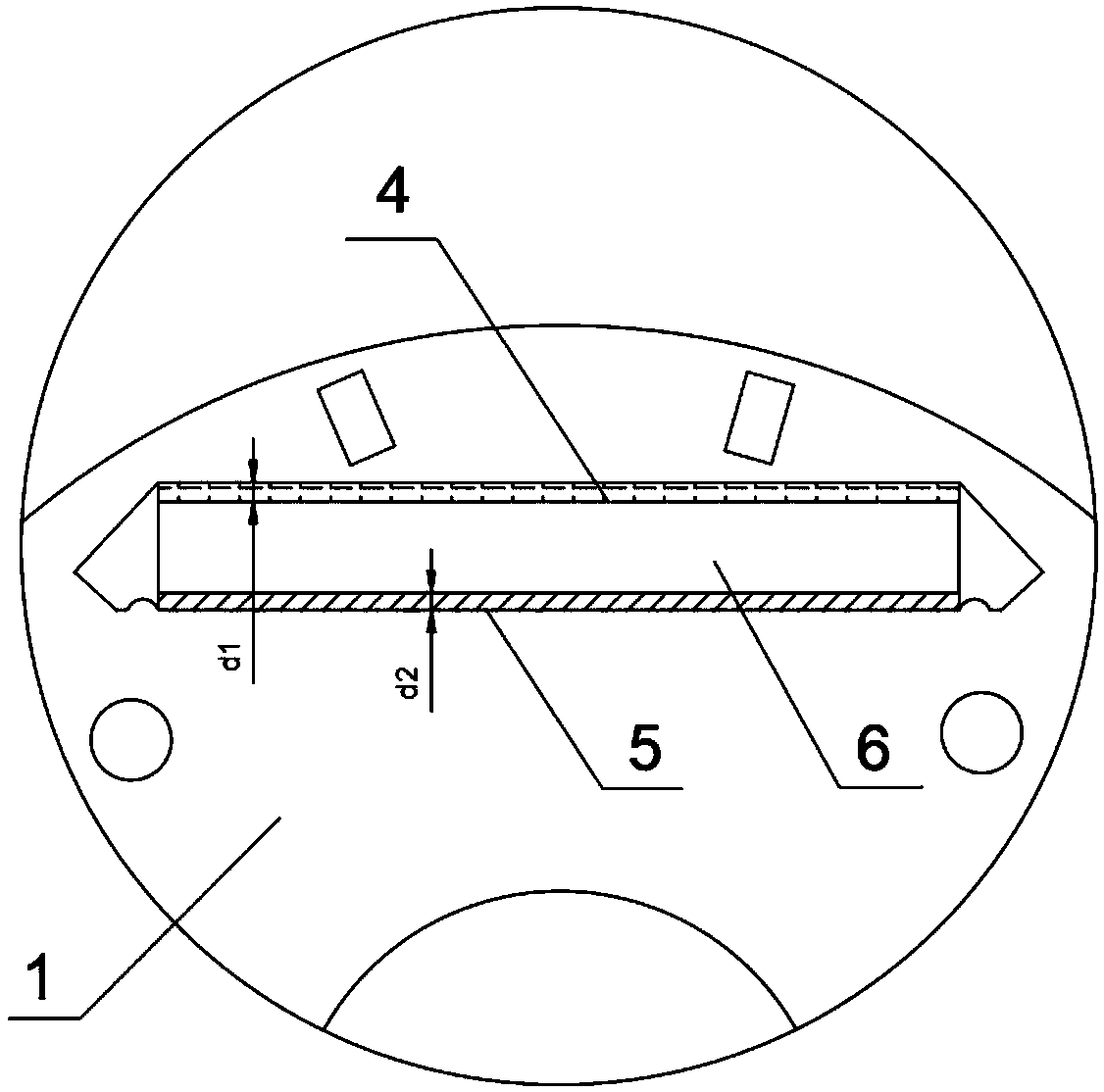
[0034] Please refer to figure 1 , figure 2 and image 3 As shown, this embodiment provides a rotor core, including a rotor body 1, the rotor body 1 is provided with at least one magnetic steel groove 2, the magnetic steel groove 2 is provided with a magnetically conductive elastic member 5 and a nonmagnetically conductive elastic member 4, and the magnetic steel The surface near the outer side of the rotor body 1 between the two ends of the slot 2 is the outer wall surface, the surface corresponding to the outer wall of the magnetic steel slot 2 is the inner wall surface, the non-magnetic conductive elastic part 4 is arranged on the outer wall surface, and the magnetic conductive elastic part 5 is arranged on the inner wall surface Above, the magnetic steel groove 2 is provided with a magnetic steel 6, and the non-magnetic conductive elastic and magnetic conductive elastic parts 5 respectively squeeze the magnetic steel 6, and the magnetic steel groove 2 is arranged on the a...

Embodiment 2

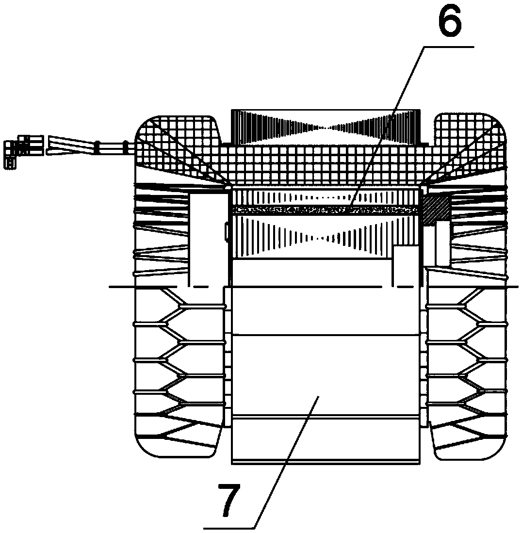
[0039] combine figure 1 , figure 2 and image 3 As shown, the present embodiment provides a motor, the motor includes a rotor core, the motor also includes a stator 7, the stator 7 is provided with a winding coil and a rotor shaft hole, the rotor core is rotatably arranged in the inner ring of the stator 7, the rotor iron The core includes a rotor body 1, four rectangular magnetic steel grooves 2 are arranged on the axial end face of the rotor body 1, and the two ends of the magnetic steel groove 2 are provided with magnetic isolation grooves 3 communicating with the magnetic steel groove 2. The surface of the groove 2 near the outer side of the rotor body 1 is the outer wall surface, the side of the magnetic steel groove 2 opposite to the outer wall surface is the inner wall surface, the non-magnetic conductive elastic part 4 is pasted on the outer wall surface, and the magnetic conductive elastic part 5 is pasted on the inner wall surface , the magnetic steel 6 is placed ...


PUM


Abstract

The invention relates to the field of electric machines, in particular to a rotor iron core and an electric machine having the same, comprising a rotor body, wherein the rotor body is provided with atleast one magnetic steel groove; The magnetic steel groove is provided with a magnetically conductive elastic member and a non-magnetically conductive elastic member; The surface between the two endsof the magnetic steel groove close to the outer side of the rotor body is an outer wall surface; The surface of the magnetic steel groove corresponding to the outer wall is an inner wall surface, thenon-magnetically conductive elastic member is arranged on the outer wall surface, and the magnetically conductive elastic member is arranged on the inner wall surface. When the rotor core rotates, the magnetically conductive elastic member and the non-magnetically conductive elastic member can change the position of the magnetic steel in the magnetic steel groove, thereby regulating the magneticflux of the rotor core.

Description

technical field [0001] The invention relates to the field of motors, in particular to a rotor core and a motor with the same. Background technique [0002] With the advancement of technology, permanent magnet synchronous motors are used more and more in manufacturing due to their own advantages; the existing permanent magnet motors are fixed due to the permanent magnet magnetomotive force, the main magnetic flux cannot be adjusted according to needs, and the operating range of the motor is narrow. The speed range is limited, and the magnetic flux obtained at low speed is small. Contents of the invention [0003] The purpose of the present invention is to provide a rotor core, which can change the position of the magnetic steel in the magnetic steel groove through the magnetic conductive elastic part and the non-magnetic conductive elastic part when the rotor core rotates, thereby adjusting the magnetic flux of the rotor core. [0004] Another object of the utility model i...

Claims


Application Information

Patent Timeline
Patent Type & Authority Applications(China)
IPC IPC(8): H02K1/27H02K21/02
CPCH02K1/276H02K21/025
Inventor 朱晓光陈华杰刘锋刘才李睿
Owner ZHUHAI GREE REFRIGERATION TECH CENT OF ENERGY SAVING & ENVIRONMENTAL PROTECTION
Why Eureka
Try Eureka