Motor flux change method
A technology of changing magnetic flux and magnetic flux, applied in the field of changing the magnetic flux of permanent magnet synchronous motor, can solve the problems of limited adjustment range, reduced power density, reduced reluctance torque, etc., to achieve the effect of controllable change of magnetic flux
- Summary
- Abstract
- Description
- Claims
- Application Information
AI Technical Summary
Problems solved by technology
Method used
Image

Examples
Embodiment 1
[0025] Embodiment 1: Motor variable magnetic flux structure with variable iron core cross-sectional shape and size
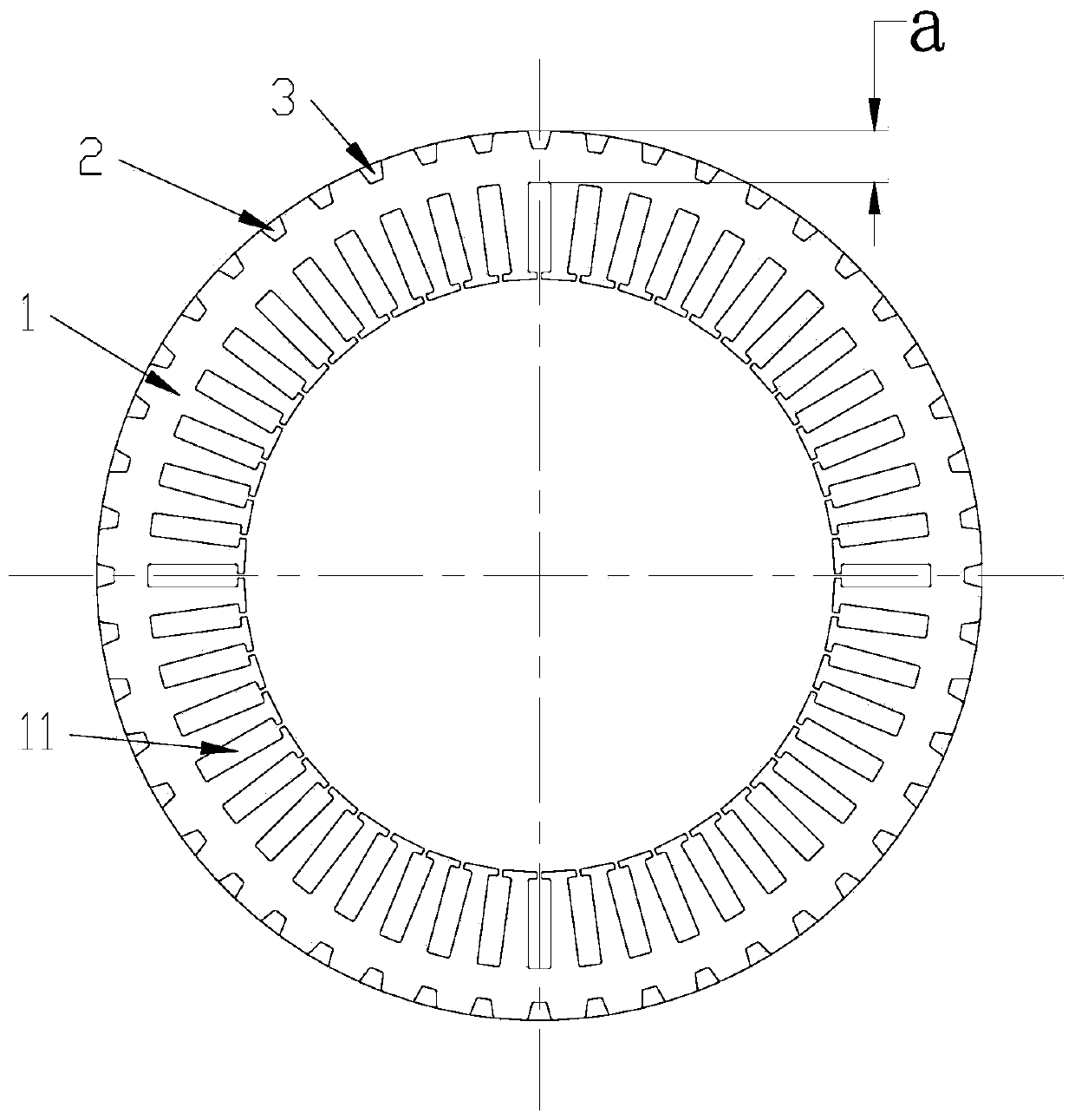
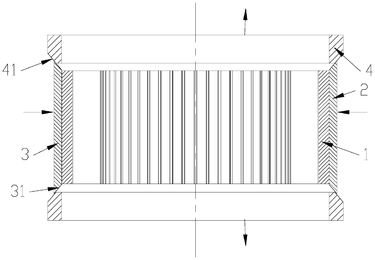
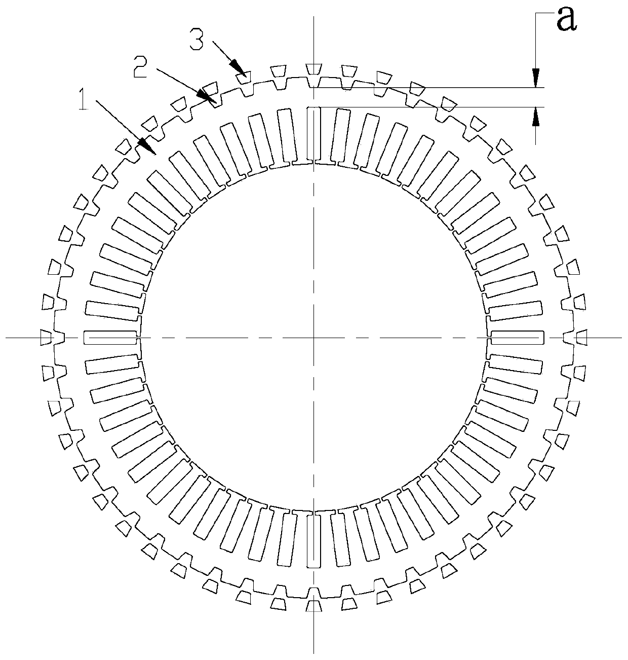
[0026] Referring to the variable magnetic flux structure of the motor shown in Figures 1 and 3, there is a flux regulating block 3 that can be embedded in the groove 2 on the outer circumference of the iron core on the stator core 1 with a wire slot 11, and the two sides of the stator core Two conical adjusting sleeves 4 are respectively arranged at the ends, and the diameter of the conical surface 41 of the conical adjusting sleeve near the end of the iron core is smaller in the axial direction of the stator, and the diameter away from the end of the iron core is larger.
[0027] Both ends of the magnetic flux regulating block 3 have tapered surfaces 31 that are in sliding contact with the tapered surfaces 41 of the two tapered regulating sleeves.
[0028] In order to keep the tapered surfaces 31 at both ends of the magnetic flux adjustment block 3 in contact w...
Embodiment 2
[0032] Embodiment 2: Variable magnetic flux structure of motor with variable gap size
[0033] see Figure 5 , On the stator core 1 with wire slot 11, there is an inlay 6 embedded in the chute 5 on the periphery of the iron core and in contact with the bottom surface of the chute, and there is a gap between the two sides of the inlay and the two sides of the chute.
[0034] By moving the insert in the circumferential direction of the stator, by changing the size of the gap between the insert and the two sides of the slide groove, the reluctance of the stator core is changed, thereby changing the stator magnetic flux.
[0035] An insert adjustment ring 7 that rotates around the stator axis is arranged on the outer periphery of the stator core, and the outer periphery of the insert 6 is fixedly connected with the inner periphery of the insert adjustment ring 7 . The outer periphery of the insert adjustment ring 7 has two ring gears 9 meshed with the insert adjustment gear shaft...
PUM
 Abstract
Description
Claims
Application Information
 - R&D
- Intellectual Property
- Life Sciences
- Materials
- Tech Scout
- Unparalleled Data Quality
- Higher Quality Content
- 60% Fewer Hallucinations
Browse by: Latest US Patents, China's latest patents, Technical Efficacy Thesaurus, Application Domain, Technology Topic, Popular Technical Reports.
© 2025 PatSnap. All rights reserved.Legal|Privacy policy|Modern Slavery Act Transparency Statement|Sitemap|About US| Contact US: help@patsnap.com