
Cam-lever-type automatic feeding device

A technology of automatic feeding and cam levers, which is applied in the direction of transportation and packaging, conveyor objects, etc., can solve the problems of inaccurate loading of workpieces to be processed, difficult workpiece driving loading, and complicated structure of feeding mechanism, etc., so as to facilitate manual operation The effects of debugging, continuous and stable feeding, and reasonable structural design

Inactive Publication Date: 2018-12-18
HUIZHOU CHENGTAI AUTOMATION TECH CO LTD
View PDF9 Cites 2 Cited by
  • Summary
  • Abstract
  • Description
  • Claims
  • Application Information

AI Technical Summary

Problems solved by technology

In the traditional processing and manufacturing process, materials are often loaded manually, but the speed of manual feeding is slow and it is considered that the placement is often not very accurate and affects the processing of the machine; at present, most of the automatic feeding mechanisms on the market have replaced manual feeding. Its structure is simple and compact, and it is more flexible and reliable when used. It can assist in the realization of fully automated machine tool processing, thereby saving labor costs and improving processing efficiency and reliability.
[0003] During the production and processing of workpieces to be processed, it is necessary to smoothly load the workpieces to be processed one by one, so that the workpieces to be processed can be processed accurately; the existing workpieces to be processed are easy to cause The workpiece cannot be loaded accurately, resulting in low processing efficiency of the workpiece to be processed, and the existing loading mechanism for the workpiece to be processed has a complex structure, and it is difficult to drive and load the workpiece continuously and smoothly, and due to the space limitation of the machine tool equipment, It is not conducive to the maintenance and replacement of the feeding mechanism; in addition, the energy consumption of the drive structure of the existing feeding mechanism is high, the energy consumption of the driving equipment is large, the service life is limited, and frequent repairs and maintenance are required; it affects the normal operation of the workpiece to be processed Production, processing and installation cannot meet the needs of production and use

Method used


Image

  • Cam-lever-type automatic feeding device
  • Cam-lever-type automatic feeding device
  • Cam-lever-type automatic feeding device

Examples


Embodiment Construction

[0016] In order to make the object, technical solution and technical effect of the present invention clearer, the present invention will be further described below in conjunction with specific embodiments. It should be understood that the specific embodiments described here are only used to explain the present invention, not to limit the present invention.

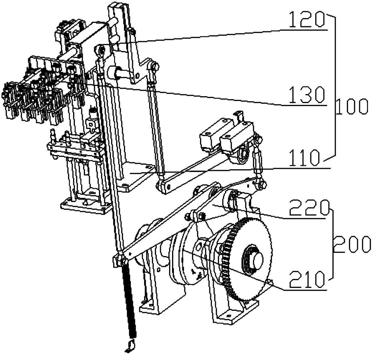
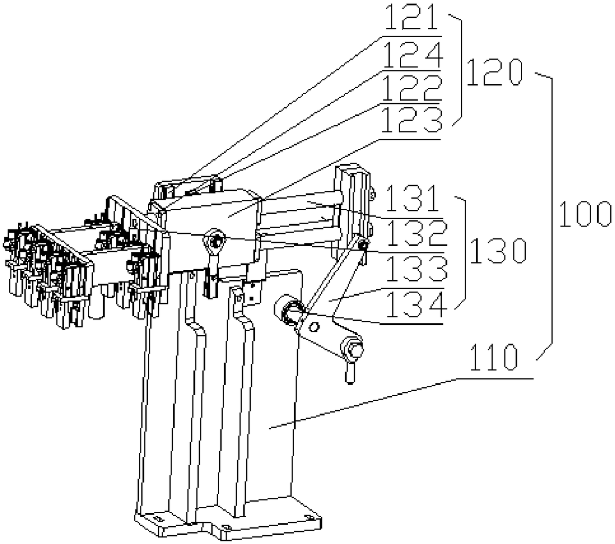
[0017] refer to figure 1 As shown, a cam lever type automatic feeding device has a frame (not shown in the figure) and a workbench (not shown in the figure) located on the frame; the workbench (not shown in the figure) Excavation) Excavate the first through hole (not shown in the figure) and the second through hole (not shown in the figure) that run through it, and its upper and lower ends are respectively provided with a feeding mechanism 100 and a power mechanism 200, The feeding mechanism 100 is installed on the table of the workbench (not shown in the figure), the power mechanism 200 is installed on the frame (not sho...


PUM


Abstract

The invention provides a cam-lever-type automatic feeding device and belongs to the technical field of machining and mounting auxiliary equipment. The cam-lever-type automatic feeding device is provided with a rack and a worktable arranged on the rack. The worktable is provided with a feeding mechanism and a power mechanism, the feeding mechanism is mounted on the table top of the worktable, and the power mechanism is mounted on the rack and comprises a cam driving assembly and a lever power assembly. The cam driving assembly drives the feeding mechanism to conduct compound motion simultaneously in the X-axis direction and the Y-axis direction by driving the lever power assembly. The cam-lever-type automatic feeding device is reasonable, simple and effective in structural design; to-be-machined workpieces can be continuously and stably fed quickly and efficiently; and in addition, the cam-lever-type automatic feeding device is low in failure rate, so that the overhauling and maintenance cost is lowered, the production efficiency of the cam-lever-type automatic feeding device is improved in an assisted mode, and the needs of production and use are met.

Description

technical field [0001] The invention relates to the technical field of mechanical processing and installation auxiliary equipment, in particular to a cam lever type automatic feeding device. Background technique [0002] Today, with the increasing cost of labor, the fully automated production of machine tools has become a development trend. In the traditional processing and manufacturing process, materials are often loaded manually, but the speed of manual feeding is slow and it is considered that the placement is often not very accurate and affects the processing of the machine; at present, most of the automatic feeding mechanisms on the market have replaced manual feeding. Its structure is simple and compact, and it is more flexible and reliable when used. It can assist in the realization of fully automatic processing of machine tools, thereby saving labor costs and improving processing efficiency and reliability. [0003] During the production and processing of workpiece...

Claims


Application Information

Patent Timeline
IPC IPC(8): B65G47/90
CPCB65G47/901
Inventor 何茂水马益金张中
Owner HUIZHOU CHENGTAI AUTOMATION TECH CO LTD
Learn More