
Wall walking device

A walking device and walking machine technology, applied in transportation, packaging, motor vehicles, etc., can solve the problems of high labor costs, casualties, and inability to turn wheels, etc., and achieve the effect of full automation

Pending Publication Date: 2018-12-18
江苏原奋科技有限公司
View PDF26 Cites 1 Cited by
  • Summary
  • Abstract
  • Description
  • Claims
  • Application Information

AI Technical Summary

Problems solved by technology

[0002] At present, there are many beautiful high-rise buildings in modern cities, but it is necessary to carry out wall work outside the high-rise buildings, such as wall washing, mainly relying on hanging boards, hanging baskets and other tools to hang the workers at high altitudes to carry out the work, which is dangerous for workers. Every year Casualties have occurred, and workers suspended at high altitudes have low efficiency and high labor costs.
In addition, for the sake of the beautiful appearance of the building, some high-altitude exterior walls are not perpendicular to the horizontal ground, but have obtuse or acute angles, and the acute-angled parts are difficult to reach through hanging baskets, so it is difficult to perform exterior wall operations, such as washing
There is no commercial product now, and existing inventions and patents, such as application number 201410671202.9, cannot realize steering. Application number 201320096470.3 is hovered by a crane and fixed by a bracket, which cannot be firmly adsorbed on the wall. Although application number 201310135905.5 has The suction cup has a sensor, but it cannot lift and put down the suction cup by itself, it only moves by a crane or a motor, and cannot work on a wall inclined at an acute angle
Others such as application number 201210451244.2, application number 201210137133.4, application number 201120035363.0, and ZL 200820155191.9 all have their own merits, but none of them can solve practical problems such as sharp-angled walls, high-altitude winds, uneven outer walls, and obstacles on the outer walls. The patent No. 201510345751.1 is to realize the alternate adsorption of the suction cups and away from the wall, which is completed by the relative movement of the two brackets in the vertical direction of the wall, so that when the crawling device walks on the wall, the whole device will be one high and one low. Movement, which increases wind resistance and the risk of falling due to gravity; patent application number 201610904433.9 has a reverse thrust fan, and has 4 wheels walking on the wall, but its wheels cannot turn, which limits its practicality; application number 201611017939.4 The patent has a reverse thrust fan with 4 wheels, which can be turned, but the steering is a steering with 2 wheels on one shaft, so that even if the vehicle does not move, the wheels are easy to touch the window frame during the turning process, and the fan turns to cause The bottom of the cleaning car produces an instant vacuum, so the bottom of the car must be in close contact with the glass, and it is difficult to maintain it during the vehicle's obstacle-crossing process; the patent application number 201710683353.X has a fan and universal wheels, but its operation process is as follows: first The machine and the universal wheel contact the wall first through the hanging rope, and then the fan pushes the cleaning part to the wall, and there is a sealing strip, and the fan generates negative pressure, so the design structure is complicated; the patent application number 201711470584.9 has a fan and a The guide wheel, but it can't turn. It is said that it has the function of automatic positioning of XYZ axis and the function of overcoming obstacles, but there is no specific description

Method used


Image

  • Wall walking device
  • Wall walking device
  • Wall walking device

Examples


Embodiment Construction

[0013] Below is a kind of implementation device in conjunction with accompanying drawing, the present invention is described in further detail.

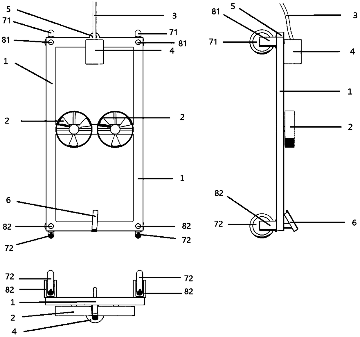
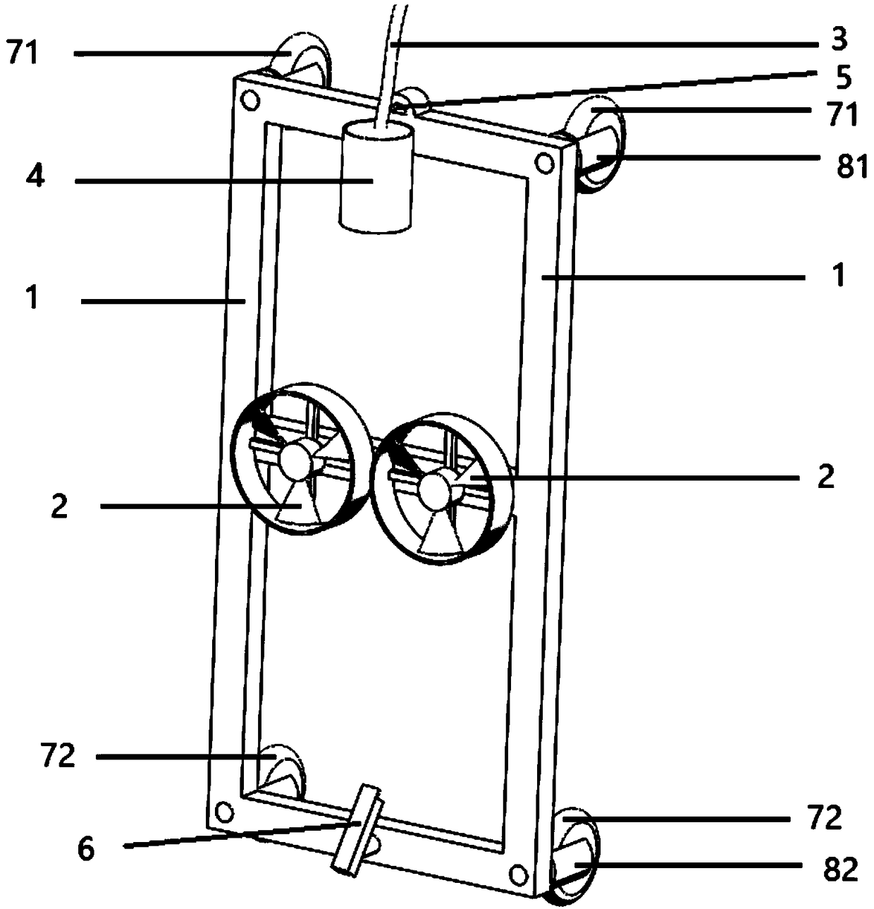
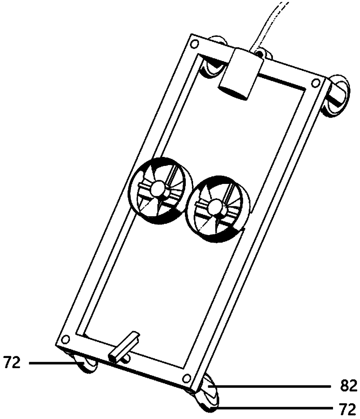
[0014] Figure 1 to Figure 9 , including:

[0015] 1. Body 1

[0016] 2. Air thruster 2

[0017] 3. Cable 3

[0018] 4. Walking controller 4

[0019] 5. Rope interface 5

[0020] 6. Camera 6

[0021] 7. Movable support device 7

[0022] 71. Upper movable support device 71

[0023] 72. Lower movable supporting device 72

[0024] 8. Steering device 8

[0025] 81. Upper steering device 81

[0026] 82. Lower steering device 82

[0027] 11. Pulley 11

[0028] 12. Bracket 12

[0029] 13. Substrate 13

[0030] 14. Wheels 14

[0031] 15. Bracket support 15

[0032] 16. Tracks 16

[0033] 17. Round track bracket 17

[0034] 18. Track bracket 18

[0035] In each figure, the movable supporting device 7 is divided into an upper movable supporting device 71 and a lower movable supporting device 72 in a specific embodiment, and ...


PUM


Abstract

A wall walking device has a high platform and a walking machine, A walking machine is suspend under that high platform by a rope, that height the platform changes the length of the suspended portion of the rope to control the walking machine to move downward, an air pushing device can allow the walking machine to be pressed on the wall by pushing air The movable support device can realize the obstacle-surmounting function through the large-radius wheel or other abnormal design, and the movable support device can realize the steering of the walking machine on the wall through the correspondingsteering device. Combined with electronic automatic control, communication and artificial intelligence technology, the whole work can be fully automated, visualized, and can be viewed and operated remotely.

Description

technical field [0001] The present invention relates to the field of wall moving machinery, more specifically, to a wall moving platform. Background technique [0002] At present, there are many beautiful high-rise buildings in modern cities, but it is necessary to carry out wall work outside the high-rise buildings, such as wall washing, mainly relying on hanging boards, hanging baskets and other tools to hang the workers at high altitudes to carry out the work, which is dangerous for workers. Every year Casualties have occurred, and workers suspended at high altitudes have low efficiency and high labor costs. In addition, for the sake of the beautiful appearance of the building, some high-altitude exterior walls are not perpendicular to the horizontal ground, but have obtuse or acute angles. The acute-angled parts are difficult to reach through hanging baskets, and it is difficult to perform exterior wall operations, such as washing. There is no commercial product now, an...

Claims


Application Information

Patent Timeline
IPC IPC(8): B62D57/024
CPCB62D57/024
Inventor 刘禄军
Owner 江苏原奋科技有限公司
Learn More