
Smart office multi-projection position conference table

A multi-projection, conference table technology, applied in the direction of tables, general furniture legs, home appliances, etc., can solve the problems of inability to adjust the projection position, delay time, damage devices, etc., to achieve convenient and fast adjustment control, fast adjustment, and ensure safety. effect used

Active Publication Date: 2018-12-18
广州响应信息科技有限公司
View PDF9 Cites 0 Cited by
  • Summary
  • Abstract
  • Description
  • Claims
  • Application Information

AI Technical Summary

Problems solved by technology

However, with the increase of business, the traditional office service model has gradually revealed many disadvantages
[0003] The most common equipment in smart office is projection equipment, which plays a more active role in enterprise work deployment and meeting agenda. Common conference room projection equipment is generally hung on the roof or placed on the conference table. On the roof, the position of the projection equipment is fixed, and it is inconvenient to adjust. If it is fixed on the table, on the one hand, it is the same as the hanging type, and the projection position cannot be adjusted. , if the projection device is simply rotated and set on the conference table, although the projection direction can be controlled, it is generally necessary to adjust the projection distance after changing the direction. If the distance is adjusted by feeling, not only the effect is poor, but also time-consuming, so a new Technical solutions to solve these problems, making the use of equipment more flexible and office more convenient and efficient

Method used


Image

  • Smart office multi-projection position conference table
  • Smart office multi-projection position conference table
  • Smart office multi-projection position conference table

Examples


Embodiment Construction

[0016] The following will clearly and completely describe the technical solutions in the embodiments of the present invention with reference to the accompanying drawings in the embodiments of the present invention. Obviously, the described embodiments are only some, not all, embodiments of the present invention. Based on the embodiments of the present invention, all other embodiments obtained by persons of ordinary skill in the art without making creative efforts belong to the protection scope of the present invention.

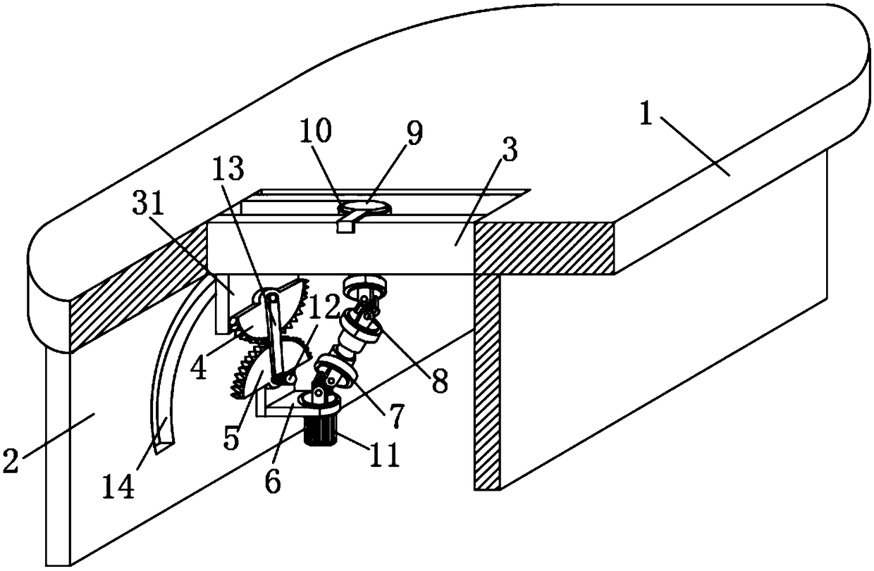
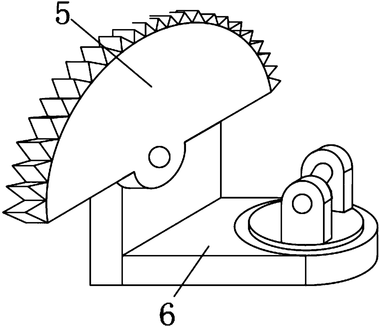
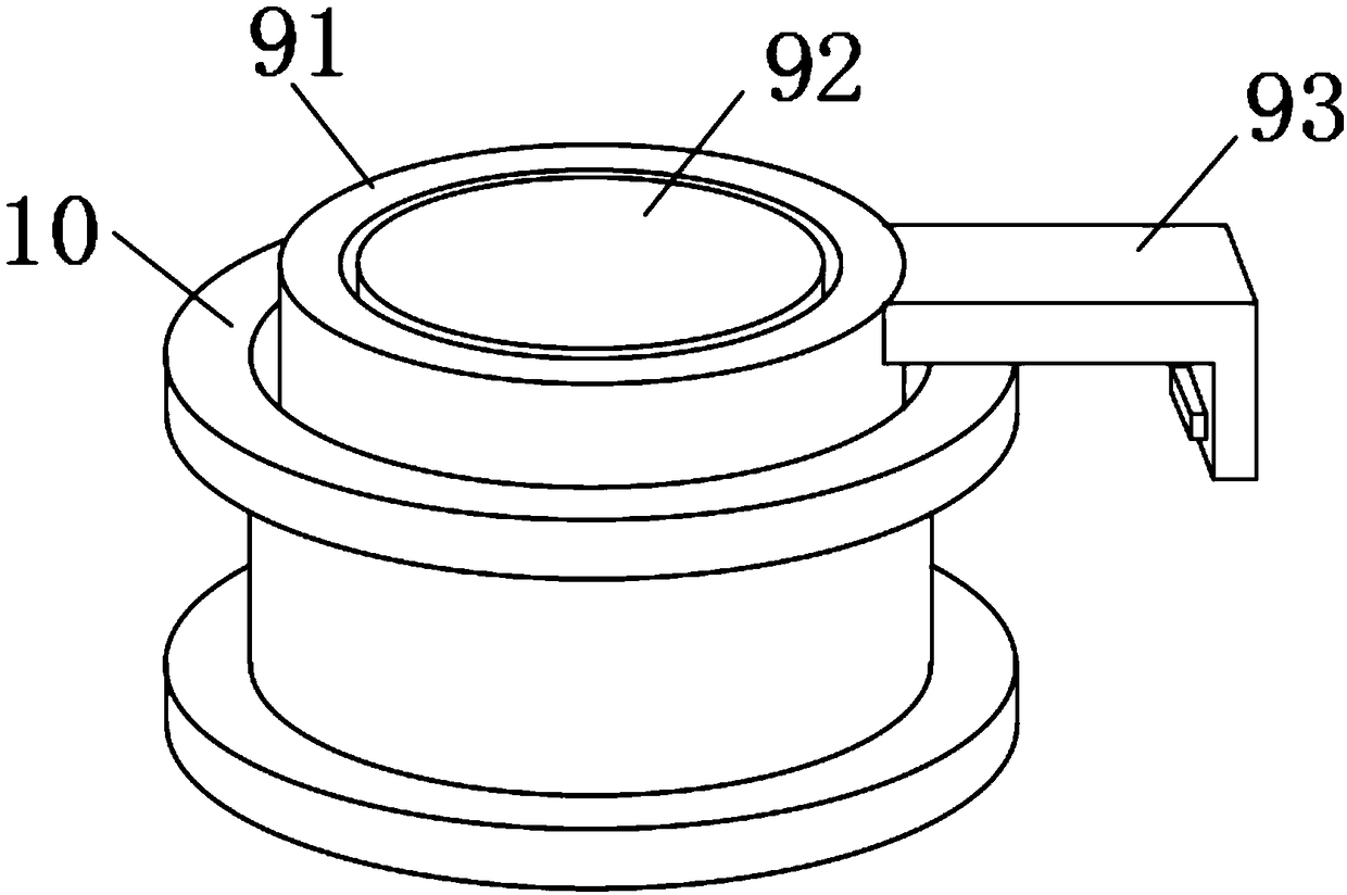
[0017] see Figure 1 to Figure 4 , the present invention provides a technical solution: a smart office multi-projection conference table, including a conference table 1 and a support frame 2, and the support frame 2 is arranged side by side and fixedly arranged under the conference table 1 along the length direction of the conference table 1. The end face of the conference desktop 1 is inlaid with a track frame 3 that can be rotatably arranged on the side of t...


PUM


Abstract

The invention discloses a smart office multi-projection position conference table comprising a conference table top and a support plate rack; a track rack arranged on the support plate rack side facein a rotary mode is embedded on the end face of the conference table top; an end face plate arranged on the support plate rack in a slide mode is formed in one piece on the end face of one side of thetrack rack; a first gear plate fixed on the surface is arranged on the lower end of the end face plate; a second gear plate mutually engaged with the first gear plate is arranged below the first gearplate; the center of the second gear plate is arranged on a mount platform in a rotary mode; the mount platform is fixedly arranged on the support plate rack surface; a first universal joint is arranged on the mount platform in a rotary mode; the upper end of the first universal joint is sleeved on a second universal joint; the other end of the second universal joint is fixedly provided with a rotary ring that is fixed on the track rack in a slide mode. The smart office multi-projection position conference table is simple in structure, easy to use, can fast adjust a projection direction and aprojection distance of the projector, is easy and fast in regulation and control, and can maintain the projector in the same time, thus ensuring the equipment usage safety.

Description

technical field [0001] The invention relates to the technical field of smart office, in particular to a smart office multi-projection conference table. Background technique [0002] Smart office is a new office mode that uses cloud computing technology to intelligently manage the software and hardware equipment required for office business, and realizes the unified deployment and delivery of enterprise application software. In the daily office of enterprises, there are often a large number of documents and documents that need to be approved Pending emails, and complex work that needs to be communicated and arranged. Therefore, enterprises are usually equipped with a complete set of office equipment to achieve resource sharing and rapid communication. However, with the increase of business, the traditional office service model has gradually revealed many disadvantages. [0003] The most common equipment in smart office is projection equipment, which plays a more active role...

Claims


Application Information

Patent Timeline
Patent Type & Authority Applications(China)
IPC IPC(8): A47B37/00A47B13/08F16M11/06F16M11/18
CPCA47B13/08A47B37/00A47B2200/0079F16M11/06F16M11/18
Inventor 范丽思廖思远陈波周振宇许开祥
Owner 广州响应信息科技有限公司
Learn More