
A flat sealing automatic compensation valve

An automatic compensation and plane sealing technology, applied in the field of compensation valves, can solve problems such as poor compensation effect, poor automatic compensation effect, complex structure, etc., achieve low leakage, strong impurity resistance, and overcome technical prejudice

Active Publication Date: 2019-02-15
烟台佳友电子机械科技有限公司
View PDF1 Cites 0 Cited by
  • Summary
  • Abstract
  • Description
  • Claims
  • Application Information

AI Technical Summary

Problems solved by technology

However, the structure of this technical solution is complicated, and the process of lifting, rotating, and re-pressing the valve core is required; the automatic compensation effect is poor, and the compensation effect is poor when the valve core is partially worn.

Method used


Image

  • A flat sealing automatic compensation valve
  • A flat sealing automatic compensation valve
  • A flat sealing automatic compensation valve

Examples


Embodiment Construction

[0036] In order to make the above objects, features and advantages of the present invention more comprehensible, specific implementations of the present invention will be described in detail below in conjunction with the accompanying drawings. In the following description, numerous specific details are set forth in order to provide a thorough understanding of the present invention. However, the present invention can be implemented in many other ways different from those described here, and those skilled in the art can make similar improvements without departing from the connotation of the present invention, so the present invention is not limited by the specific embodiments disclosed below.

[0037]Unless otherwise defined, all technical and scientific terms used herein have the same meaning as commonly understood by one of ordinary skill in the technical field of the invention. The terminology used herein in the description of the present invention is only for the purpose of ...


PUM


Abstract

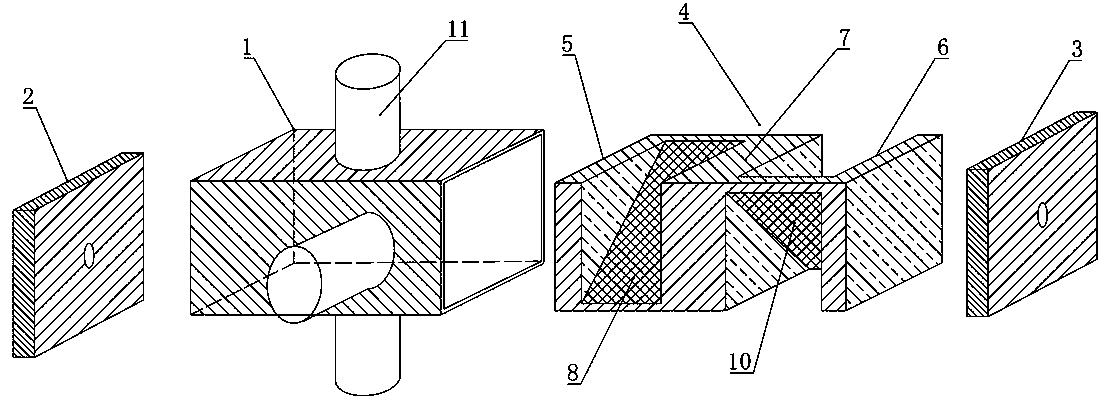
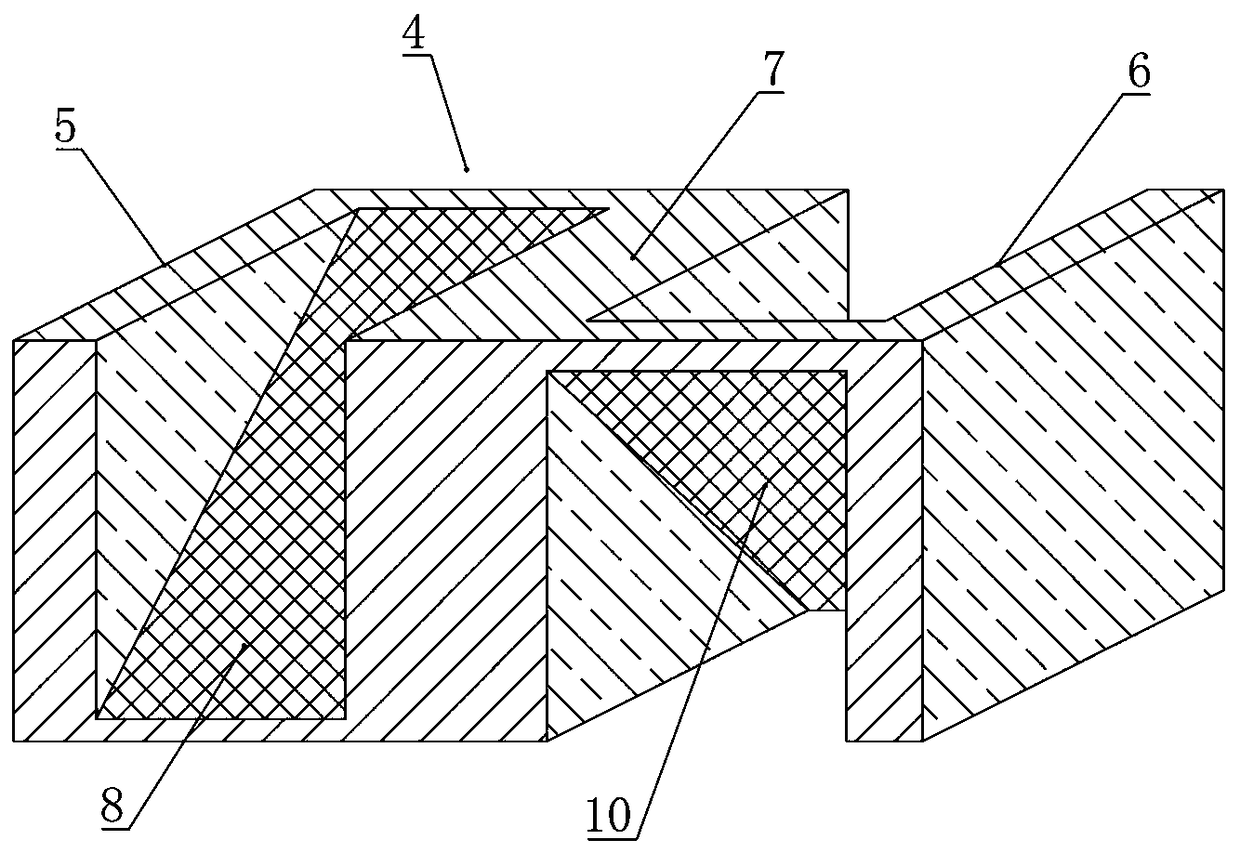
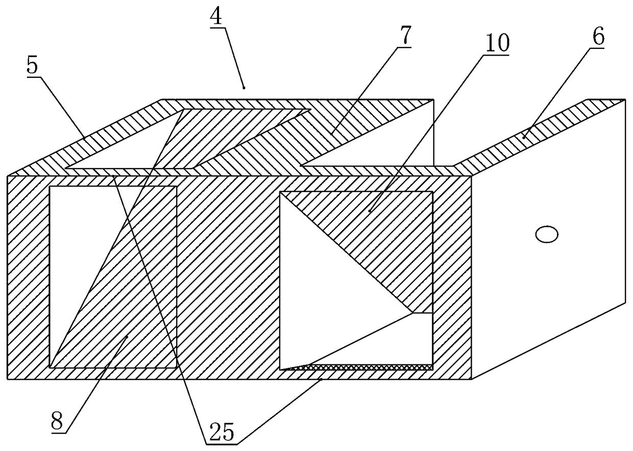
The invention discloses an automatic plane seal compensation valve. A valve element assembly moves left and right in a valve body, and the valve body limits internal rotation of the valve element assembly in the valve body. The contours of the matching surfaces of the valve body and the valve element assembly are the same and are shaped like a n-side polygon, and the n-side polygon can meet the following conditions that 1, each side is a straight line; and 2, a plurality of sides in all the sides are straight lines, and the rest of sides are curves. A space for containing the valve element assembly is formed among a left end cover, a right end cover and the valve body, a left valve plate is connected between a left piston and a middle partition plate, a right valve plate is connected between a right piston and the middle partition plate, the middle partition plate is connected between the left valve plate and the right valve plate, and the left valve plate and the right valve plate aredistributed in a crossed manner. According to the automatic plane seal compensation valve, the defect that in the prior art, leakage cannot be compensated after wear occurs is overcome, and meanwhilethe technical prejudice of technicians in the field is also overcome. When the valve element assembly is worn, automatic compensation can be achieved, low leakage is achieved, and the automatic planeseal compensation valve is simple in structure and high in impurity-resistant capacity.

Description

technical field [0001] The invention relates to the technical field of compensation valves, in particular to a flat sealing automatic compensation valve. Background technique [0002] A valve is usually a device that uses a movable part to open, close or partially block one or more openings or passages so that liquid, air or other airflow or a large amount of loose material can flow out, block or be regulated. The valve core assembly in the prior art can rotate, not only has large fluid resistance and large leakage, but also has a complex structure and troublesome manufacture, and once worn, it cannot be automatically compensated, has poor resistance to impurities, and is easy to get stuck. [0003] Patented a screw-driven conical rotary valve, the publication number is CN107269874A, which discloses a fully sealed fluid control, or flow direction switching, which can realize fluid control in chemical, petroleum, air-conditioning, and water systems, including the valve body, ...

Claims


Application Information

Patent Timeline
Patent Type & Authority Patents(China)
IPC IPC(8): F16K11/065F16K31/04
CPCF16K11/065F16K31/04
Inventor 贾培育
Owner 烟台佳友电子机械科技有限公司
Learn More