
Comb type breakwater system capable of achieving wave power generation

A breakwater and wave energy technology, applied in breakwaters, ocean energy power generation, jetties, etc., can solve problems such as high construction costs, restrictions on the popularization and use of oscillating water column and oscillating buoy type power generation devices, and low energy harvesting efficiency, achieving enhanced continuous performance, reduce the risk of damage to the wing plate, and improve the effect of wave dissipation

Pending Publication Date: 2018-12-14
HARBIN ENG UNIV
View PDF0 Cites 7 Cited by
  • Summary
  • Abstract
  • Description
  • Claims
  • Application Information

AI Technical Summary

Problems solved by technology

The oscillating water column type and the oscillating buoy type power generation device have the advantages of simple structure and good wave energy conversion performance, but the energy harvesting efficiency of the two power generation devices is low, and the construction cost is high. Popularization and Application of Oscillating Float Generator

Method used


Image

  • Comb type breakwater system capable of achieving wave power generation
  • Comb type breakwater system capable of achieving wave power generation
  • Comb type breakwater system capable of achieving wave power generation

Examples


Embodiment Construction

[0024] The technical scheme of the present invention is described in detail below in conjunction with accompanying drawing:

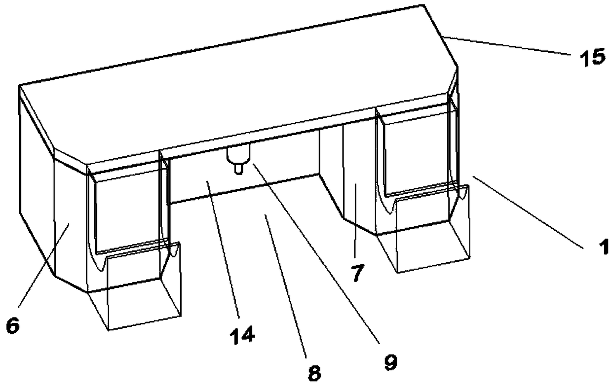
[0025] The PU-OWC&OB&CTBW system is placed on the riprap bed laid on the seabed, and consists of several units arranged continuously along the axial direction of the breakwater, such as figure 1 shown. The PU-OWC&OB&CTBW system consists of three parts: PU-OWC power generation device, oscillating buoy type power generation device and improved comb breakwater. The improved comb breakwater comprises a caisson 6, a diversion wall 7, a wing plate 14, and a breast wall 15, wherein the caissons 6 are arranged at intervals along the axial direction of the breakwater, and the wing plate 14 is arranged on the back wave side between adjacent caissons; the breast wall 15 It is installed above the caisson 6 and the wing plate 14; the PU-OWC power generation device 1 is placed on the wave-facing side of the caisson, and consists of a vertical upper wave breaker 2, a...


PUM


Abstract

The invention provides a comb type breakwater system capable of achieving wave power generation, and belongs to the field of ocean power generation. The comb type breakwater system capable of achieving wave power generation comprises an oscillating water column type power generation device, an oscillating buoy type wave power generation device and an improved comb type breakwater system body, wherein the improved comb type breakwater system body is arranged on a riprap foundation bed laid on the seabed, the oscillating water column type power generation device (short for PU-OWC) is arranged onthe wave coming side of caissons to be used for converting wave energy into electric energy. The oscillating buoy type wave power generation device is arranged in a comb type breakwater wave dissipating chamber and is fixed to a cross beam between the two caissons, and a buoy moves up and down along waves to convert mechanical energy into electric energy. According to the comb type breakwater system capable of achieving wave power generation, the improved comb type breakwater system body is used as the main structure, so that a constant condition is provided for the PU-OWC power generation device and the oscillating buoy type power generation device while a dock basin is maintained stable. Wave energy is converted into electric energy by the PU-OWC power generation device and the oscillating buoy type power generation device, so that the overall wave dissipating effect of the comb type breakwater system is improved, and the structural reliability is improved.

Description

technical field [0001] The invention relates to a comb type breakwater system which takes into account wave energy power generation. It specifically relates to a comb-type breakwater system that combines oscillating water column type and oscillating buoy type wave energy generation, that is, the PU-OWC&OB&CTBW system (PU OscillatingWater Column&Oscillation Buoy&Comb Type Breakwater), which belongs to the field of marine power generation. technical background [0002] The development of marine science and technology is an important measure to build a powerful marine country. In order to improve the ability to develop and utilize ocean energy, promote the industrialization of ocean energy technology, and expand the space for the blue economy, the State Oceanic Administration issued my country's first special plan for ocean energy development (hereinafter referred to as the "plan"). The "Plan" points out the promotion of the construction of an island (reef) renewable energy mu...

Claims


Application Information

Patent Timeline
IPC IPC(8): E02B3/06E02B8/06F03B13/14F03B13/18
CPCF03B13/142F03B13/18E02B3/062E02B8/06Y02A10/11Y02E10/30
Inventor 李明伟张娜耿敬耿贺松赵玄烈张洋张立东薛蓉周加春张泰
Owner HARBIN ENG UNIV
Learn More