Jacking device for roller shaft

A jacking device and roller shaft technology, applied in the direction of the hoisting device, etc., can solve the problems of low installation accuracy of the clamping table, unfavorable roller shaft jacking, and potential safety hazards, so as to reduce the occurrence of potential safety accidents, improve the safety of use, The effect of high installation accuracy

Inactive Publication Date: 2018-12-14
WUHU DINGHAN REMFR TECH
View PDF3 Cites 0 Cited by
  • Summary
  • Abstract
  • Description
  • Claims
  • Application Information

AI Technical Summary

Problems solved by technology

However, most of the driving or hoisting equipment is a steel cable structure, which has poor stability during hoisting, low installation accuracy with the clamping table, and the roller shaft is easy to shake during the lifting and lowering process, which is highly dangerous and has great potential safety hazards, which is not conducive to Lifting of the roller

Method used


Image

  • Jacking device for roller shaft
  • Jacking device for roller shaft

Examples


Embodiment Construction

[0014] In order to make the technical means, creative features, goals and effects achieved by the present invention easy to understand, the present invention will be further elaborated below.

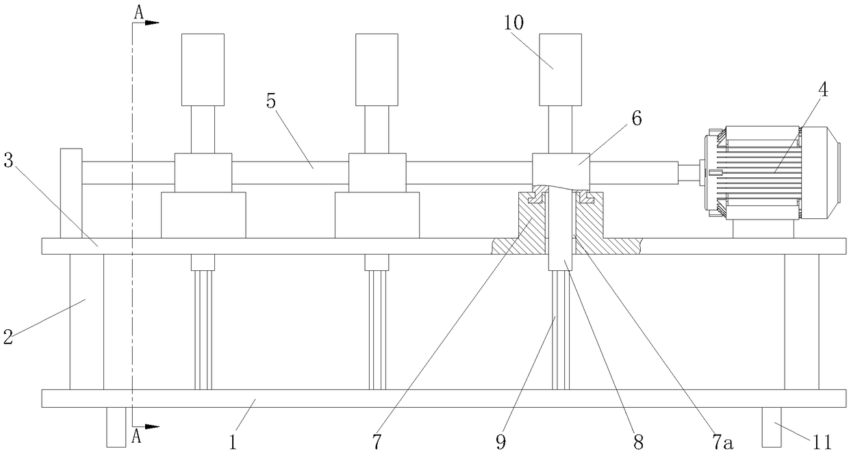
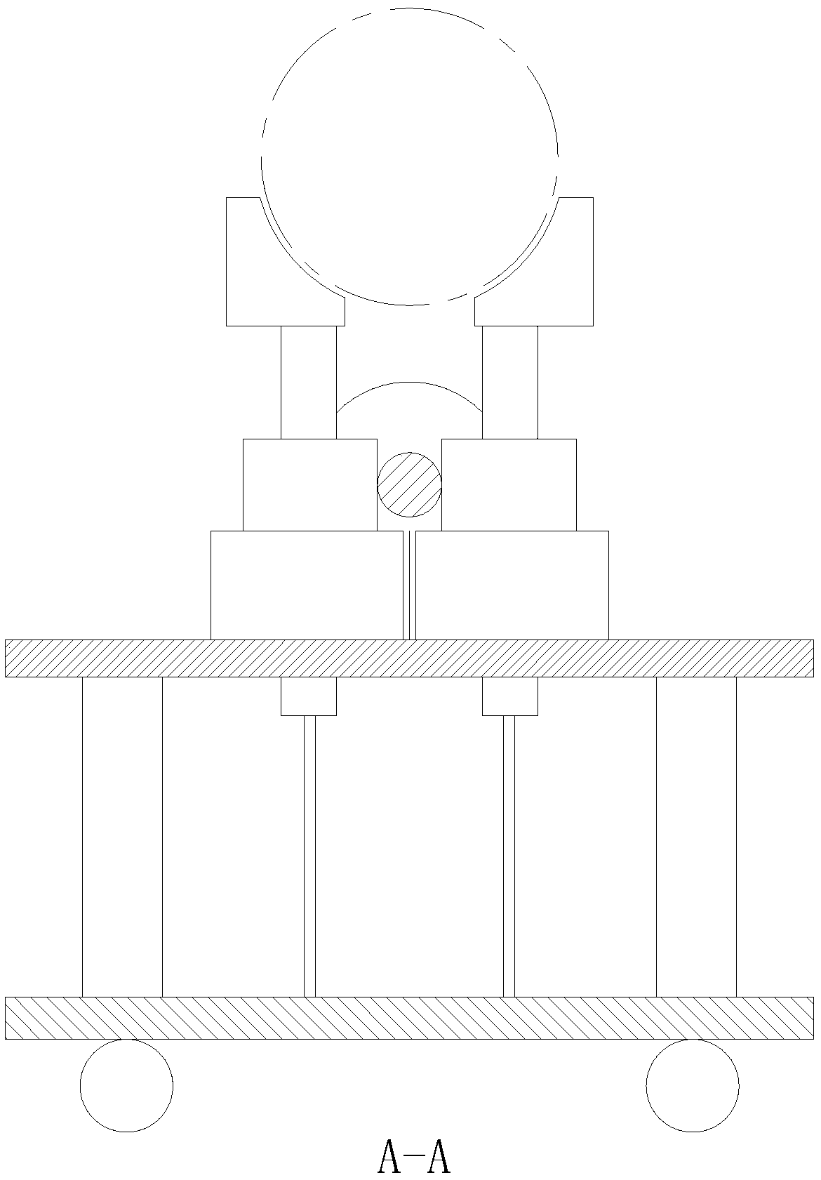
[0015] Such as Figure 1 to Figure 2 As shown, a jacking device for a roller shaft includes a base plate 1, a column 2 fixed on the base plate 1, a support platform 3 connected to the top of the column 2, a servo motor 4 is installed on the support platform 3, and the servo motor 4 is installed on the support platform 3. The drive shaft of the motor 4 is connected with a long worm 5, and the long worm 5 is evenly distributed with three elevating mechanisms along the direction of its own axis; The worm wheel 6 is rotatably connected with a mounting seat 7 fixed on the support platform 3, the mounting seat 7 is provided with an avoidance vertical hole 7a coaxially distributed with the worm wheel 6, and the middle part of the worm wheel 6 is threaded to pass through the avoidance vertical ...


PUM


Abstract

The invention relates to a jacking device for a roller shaft. The jacking device for the roller shaft comprises a bottom plate, stand columns fixed on the bottom plate, and a supporting table connected to the tops of the stand columns, a servo motor is installed on the supporting table, a driving shaft of the servo motor is connected with a long worm, and three lifting mechanisms are uniformly distributed on the long worm in the axis direction of the long worm; each lifting mechanism comprises two worm wheels which are distributed in a front-back mode and are meshed with the long worm, the worm wheels are rotationally connected with mounting seats fixed on the supporting table, and avoiding vertical holes which are distributed coaxial with the worm wheels are formed in the mounting seats;and the middles of the worm whees are in threaded connection with long screw rods penetrating through the avoiding vertical holes, guide rods which are fixed on the bottom plate and limit the rotationof the bottom plate are arranged at the bottoms of the long screw rods in a sliding fit mode, and supporting blocks are fixed at the tops of the long screw rods. According to the jacking device for the roller shaft, when the roller shaft is lifted, the higher stability is achieved, the mounting precision relative to a clamping table is high, so that the use safety is greatly improved, and the whole device has the advantages of being simple to operate, convenient to use and capable of moving.

Description

technical field [0001] The invention relates to the technical field of lifting machinery, in particular to a jacking device for a roller shaft. Background technique [0002] Roller shaft, generally refers to the general name of the cylindrical parts that can roll on the machine. Generally, the roller shaft is large and heavy, and it is difficult to move and lift. It needs to be installed with the clamping table after being lifted by driving or lifting equipment. However, most of the driving or hoisting equipment is a steel cable structure, which has poor stability during hoisting, low installation accuracy with the clamping table, and the roller shaft is easy to shake during the lifting and lowering process, which is highly dangerous and has great potential safety hazards, which is not conducive to Roller jacking. Contents of the invention [0003] In order to avoid and solve the above technical problems, the present invention proposes a jacking device for a roller. [0...

Claims


Application Information

Patent Timeline
Patent Type & Authority Applications(China)
IPC IPC(8): B66F3/46B66F3/44
Inventor 程敬卿刘泽军薛卫昌
Owner WUHU DINGHAN REMFR TECH
Why Eureka
Try Eureka