An assembly method for the assembly accuracy of instrument components based on image detection

A technology for instrument components and assembly accuracy, which is applied in the field of assembly accuracy of instrument components, which can solve the problems of low loss rate of instrument components, low assembly cost, and difficulty in ensuring accuracy, and achieve the effect of easy guarantee of assembly accuracy and high assembly accuracy

Active Publication Date: 2020-05-08
CHENGDU JIANGYE OPTOELECTRONICS TECH
View PDF9 Cites 0 Cited by
  • Summary
  • Abstract
  • Description
  • Claims
  • Application Information

AI Technical Summary

Problems solved by technology

[0003] The purpose of the present invention is to provide a precision assembly method for instrument components based on image detection, aiming at the defects of low assembly efficiency, high loss rate, high assembly cost, and difficulty in ensuring precision in the traditional instrument assembly assembly operations, and to realize The function of high-precision, automatic and fast assembly of instrument assembly components has the beneficial effects of high assembly efficiency, high assembly precision, low loss rate of instrument components, and low assembly cost

Method used


Image

  • An assembly method for the assembly accuracy of instrument components based on image detection
  • An assembly method for the assembly accuracy of instrument components based on image detection
  • An assembly method for the assembly accuracy of instrument components based on image detection

Examples


Embodiment 1

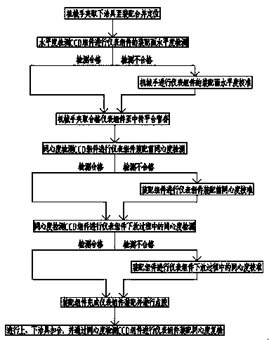
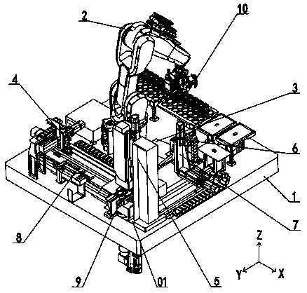
[0040] An assembly method for the assembly accuracy of instrument components based on image detection. The instrument components are assembled through the instrument component assembly precision control device. The instrument components include a lower frame, a swing piece, and an upper frame. The lower fixture and upper fixture, such as figure 1 and figure 2 shown, including the following steps:

[0041] Step A. First, the manipulator 2 clamps and removes the jig from the storage table assembly 10 and prevents it from being placed on the assembly platform 9, and the lower jig is positioned and fixed on the assembly platform 9;

[0042] Step B, then, the manipulator 2 sequentially removes the lower frame, the swing plate, and the upper frame from the storage table assembly 10 to the top of the levelness detection CCD assembly 6, and then performs the lower frame, the swing plate, and the upper frame through the levelness detection CCD assembly 6 in sequence. The levelness o...

Embodiment 2

[0053]This embodiment is further optimized on the basis of Embodiment 1. In the step C, the reclaiming device sequentially clamps the instrument assembly from the transfer platform 3 to the top of the lower fixture, and then performs the first stage of concentricity calibration. The degree detection CCD component 5 performs the first-stage concentricity detection between the instrument assembly and the lower fixture and between the instrument assemblies in turn, and performs concentricity calibration; then performs the second-stage concentricity calibration, and the reclaimer grabs The instrument assembly is slowly assembled downward on the lower jig, and the concentricity is detected in real time by the concentricity detection CCD assembly 5 during the slow downward movement of the instrument assembly, and real-time correction is performed.

[0054] Other parts of this embodiment are the same as those of Embodiment 1 above, so details are not repeated here.

Embodiment 3

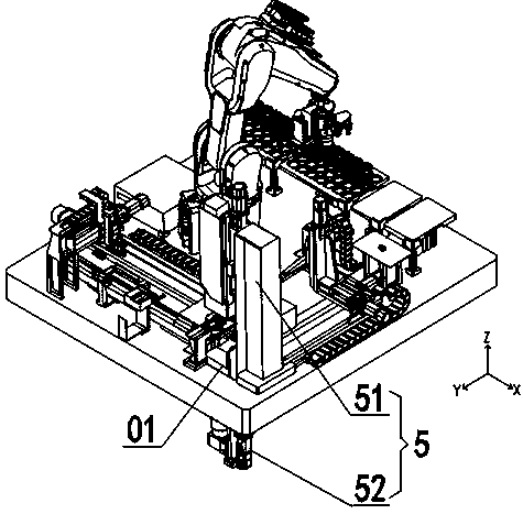
[0056] This embodiment is further optimized on the basis of above-mentioned embodiment 1 or 2, such as image 3 As shown, the concentricity detection CCD assembly 5 includes an upper concentricity detection CCD51 and a lower concentricity detection CCD52, and the upper concentricity detection CCD51 and the lower concentricity detection CCD52 are symmetrically installed on the upper and lower sides of the through hole 01 of the table 1 On both sides, the lens axes of the upper concentricity detection CCD51 and the lower concentricity detection CCD52 are coaxially arranged and vertically pass through the through hole 01; the shooting pixels of the upper concentricity detection CCD51 and the lower concentricity detection CCD52 are 29 million, concentric The degree repeatability error accuracy is 0.003888mm, and the field of view is 25mm×25mm; the shooting pixels of the levelness detection CCD assembly 6 are 5 million, the pixel accuracy is 0.0069mm, and the calibration accuracy is...


PUM


Abstract

The invention discloses an image-detection-based assembling method capable of guaranteeing instrument assembly assembling precision. The assembling method is used for assembling instrument assembliesby using an instrument assembly assembling precision control device on the basis of image detection. The assembling method the comprises the following steps that step A, a lower jig is clamped to an assembling table for positioning and fixing; step B, the instrument assemblies are clamped to a levelness detection CCD assembly for assembly surface levelness detection and calibration as well as temporary storage; step C, an assembling assembly sucks the instrument assemblies to a position above the assembling table, a concentricity detection CCD assembly is used for performing concentricity detection and calibration of the instrument assemblies before assembling and during the lowering process, and then glue dispensing is carried out in sequence; step D, an upper jig and the lower jig are buckled and combined, and then the concentricity detection CCD assembly is used for performing assembling concentricity re-inspection of the instrument assemblies. The assembling method has the beneficial effects that the assembling precision is higher, the assembling precision is easy to guarantee, the relative positions of the instrument assemblies can be adjusted in real time, the assembling costis low, the assembling efficiency is high, the automation degree is high, and the assembling time is short.

Description

technical field [0001] The invention relates to the technical field of high-precision assembly of instrument components, in particular to an assembly method for assembly accuracy of instrument components based on image detection. Background technique [0002] The assembly of instrument components is a complex process with extremely high precision requirements. In the traditional assembly of instrument components, in order to ensure the assembly accuracy of the instrument assembly components, the instrument assembly components are generally assembled by manufacturing jigs corresponding to the instrument assembly components. Positioning and ensuring the assembly accuracy between the instrument assembly components through the assembly accuracy between the fixtures, although this method can guarantee the assembly accuracy of the instrument assembly components to a certain extent, but this method also has low assembly efficiency, The defects of high loss rate of instrument assemb...

Claims


Application Information

Patent Timeline
Patent Type & Authority Patents(China)
IPC IPC(8): B23P21/00B23P19/10
CPCB23P19/102B23P21/004
Inventor 李凯王昱岳永承
Owner CHENGDU JIANGYE OPTOELECTRONICS TECH
Why Eureka
Try Eureka