Image-detection-based assembling method capable of guaranteeing instrument assembly assembling precision
A technology for instrument components and assembly accuracy, which is applied in the field of assembly accuracy of instrument components, can solve the problems of low assembly cost, low rate of damage reported for instrument components, and high rate of reported damage, and achieves high assembly accuracy and easy guarantee of assembly accuracy.
- Summary
- Abstract
- Description
- Claims
- Application Information
AI Technical Summary
Problems solved by technology
Method used
Image
Examples
Embodiment 1
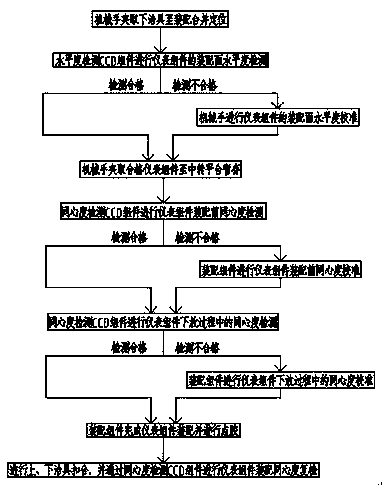
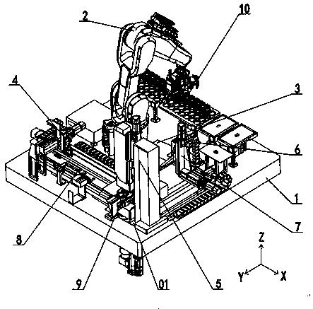
[0040] An assembly method for the assembly accuracy of instrument components based on image detection. The instrument components are assembled through the instrument component assembly precision control device. The instrument components include a lower frame, a swing piece, and an upper frame. The lower fixture and upper fixture, such as figure 1 and figure 2 shown, including the following steps:
[0041] Step A. First, the manipulator 2 clamps and removes the jig from the storage table assembly 10 and prevents it from being placed on the assembly platform 9, and the lower jig is positioned and fixed on the assembly platform 9;
[0042] Step B, then, the manipulator 2 sequentially removes the lower frame, the swing plate, and the upper frame from the storage table assembly 10 to the top of the levelness detection CCD assembly 6, and then performs the lower frame, the swing plate, and the upper frame through the levelness detection CCD assembly 6 in sequence. The levelness o...
Embodiment 2
[0053]This embodiment is further optimized on the basis of Embodiment 1. In the step C, the reclaiming device sequentially clamps the instrument assembly from the transfer platform 3 to the top of the lower fixture, and then performs the first stage of concentricity calibration. The degree detection CCD component 5 performs the first-stage concentricity detection between the instrument assembly and the lower fixture and between the instrument assemblies in turn, and performs concentricity calibration; then performs the second-stage concentricity calibration, and the reclaimer grabs The instrument assembly is slowly assembled downward on the lower jig, and the concentricity is detected in real time by the concentricity detection CCD assembly 5 during the slow downward movement of the instrument assembly, and real-time correction is performed.
[0054] Other parts of this embodiment are the same as those of Embodiment 1 above, so details are not repeated here.
Embodiment 3
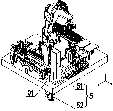
[0056] This embodiment is further optimized on the basis of above-mentioned embodiment 1 or 2, such as image 3 As shown, the concentricity detection CCD assembly 5 includes an upper concentricity detection CCD51 and a lower concentricity detection CCD52, and the upper concentricity detection CCD51 and the lower concentricity detection CCD52 are symmetrically installed on the upper and lower sides of the through hole 01 of the table 1 On both sides, the lens axes of the upper concentricity detection CCD51 and the lower concentricity detection CCD52 are coaxially arranged and vertically pass through the through hole 01; the shooting pixels of the upper concentricity detection CCD51 and the lower concentricity detection CCD52 are 29 million, concentric The degree repeatability error accuracy is 0.003888mm, and the field of view is 25mm×25mm; the shooting pixels of the levelness detection CCD assembly 6 are 5 million, the pixel accuracy is 0.0069mm, and the calibration accuracy is...
PUM
 Abstract
Description
Claims
Application Information
 - Generate Ideas
- Intellectual Property
- Life Sciences
- Materials
- Tech Scout
- Unparalleled Data Quality
- Higher Quality Content
- 60% Fewer Hallucinations
Browse by: Latest US Patents, China's latest patents, Technical Efficacy Thesaurus, Application Domain, Technology Topic, Popular Technical Reports.
© 2025 PatSnap. All rights reserved.Legal|Privacy policy|Modern Slavery Act Transparency Statement|Sitemap|About US| Contact US: help@patsnap.com


