


Quick Research
Generate reliable direction feasibility study reports for your R&D in just a few steps.

Technical Q&A
Discover and master advanced knowledge NOW. Basics, ideas, possibilities, all at once.

Find Solutions
As an expert in R&D theories, this can generate solutions to your technical problems instantly.

Evaluate Feasibility
Analyze your overall solution with one click, know your potential R&D risks in advance.

Monitor Landscape
Get weekly tech updates, stay abreast of the latest tech innovations and key insights.
Tractor and traction control device
A retractor and drawbar technology, applied in the field of medical devices, can solve the problems of cumbersome operation, poor treatment effect, complex structure, etc., and achieve the effect of small operation difficulty, avoiding breakage and dislocation, and simple structure
- Summary
- Abstract
- Description
- Claims
- Application Information
AI Technical Summary
Problems solved by technology
Method used
Image

Examples
Embodiment 1
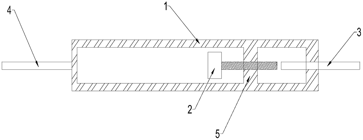
[0031] Such as figure 1 As shown, the tractor 100 in this embodiment includes a housing 1, a magnetic induction driving part 2 and a movable traction rod 3, a cavity is arranged inside the housing 1, and the magnetic induction driving part 2 is arranged in the housing 1, and the magnetic induction driving Part 2 is a magnet or a coil, preferably a coil. One end of the casing 1 is provided with a fixed drawbar 4, which is connected to the titanium plate 14 during use, and the other end of the casing 1 is provided with a movable hole. The inside of the housing 1 is provided with a first fixing part 5, the first fixing part 5 is connected to the inner wall of the housing 1, preferably, the first fixing part 5 is integrally formed with the housing 1, and the first fixing part 5 is provided with threads The through hole, the axis of the threaded through hole is the same line as the axis of the housing 1, the threaded through hole is provided with a threaded rod 6, and the threaded...
Embodiment 2
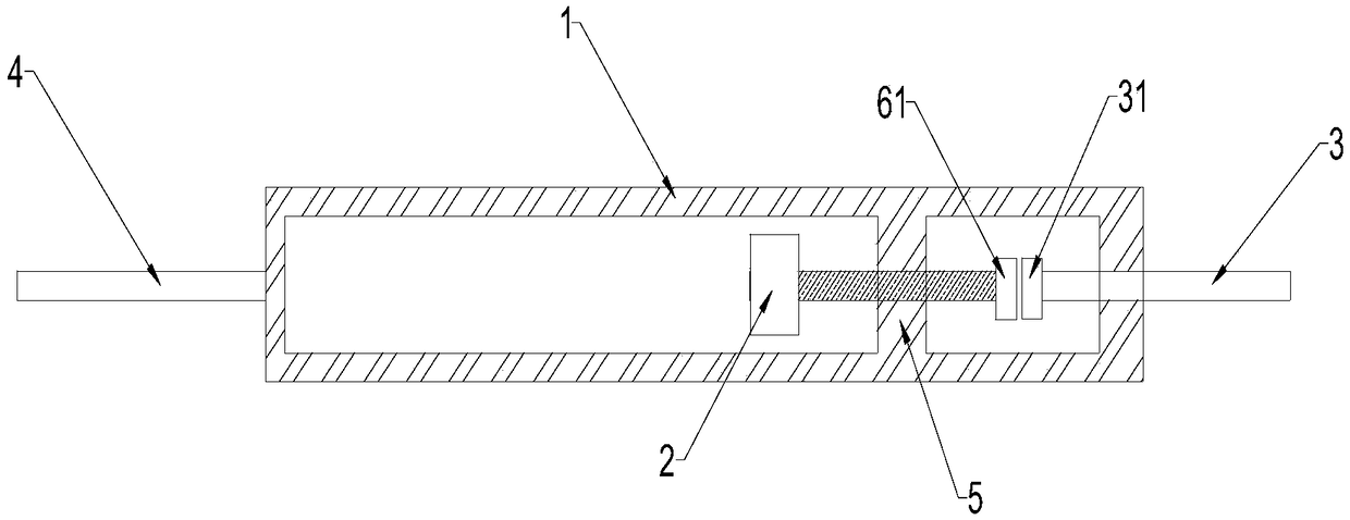
[0034] Such as figure 2 As shown, this embodiment is based on Embodiment 1. The difference between this embodiment and Embodiment 1 is that the end of the other end of the threaded rod 6 extends radially outwards to form a circular first contact portion 61, which is movable One end of the draw rod 3 extends radially outward to form a circular second contact portion 31 . By arranging the first contact portion 61 and the second contact portion 31 , the contact surface between the threaded rod 6 and the movable drawbar 3 is enlarged, so that the movable drawbar 3 is pushed out of the casing 1 more smoothly.
[0035] Further, the movable traction rod 3 in this embodiment is a square rod, and correspondingly, the movable hole of the housing 1 is a square hole. When the movable drawbar 3 protrudes from the housing 1, the movable drawbar 3 can be prevented from rotating axially through the cooperation of the movable hole of the housing 1 and the square hole, and the movable drawbar...
Embodiment 3
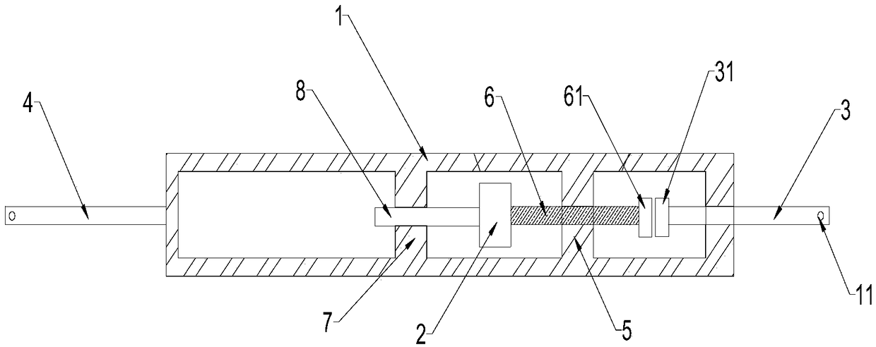
[0037] Such as image 3 As shown, this embodiment is based on Embodiment 2. The difference between this embodiment and Embodiment 2 is that a second fixing part 7 is also provided inside the housing 1, and the movable hole provided by the second fixing part 7 A balance pole 8 is pierced, and one end of the balance pole 8 is connected with the magnetic induction driving part 2 . By arranging the balance bar 8, the two ends of the magnetic induction driving part 2 can be rotated in a more balanced manner, and the rotation can be more stable.
[0038] Further, the other end of the movable drawbar 3 and the end of the fixed drawbar 4 away from the housing 1 are respectively provided with connecting holes 11, and the setting of the connecting holes 11 can facilitate the installation of the tractor 100. Titanium nails are driven into the interior to connect the titanium plate 14 with the movable drawbar 3 and the fixed drawbar 4, which greatly shortens the installation time of the ...
PUM
 Abstract
Description
Claims
Application Information
 - R&D Engineer
- R&D Manager
- IP Professional
- Industry Leading Data Capabilities
- Powerful AI technology
- Patent DNA Extraction
Browse by: Latest US Patents, China's latest patents, Technical Efficacy Thesaurus, Application Domain, Technology Topic, Popular Technical Reports.
© 2024 PatSnap. All rights reserved.Legal|Privacy policy|Modern Slavery Act Transparency Statement|Sitemap|About US| Contact US: help@patsnap.com