Method, device and system for controlling camera equipment

A technology for camera equipment and equipment control, which is applied in the field of communication, can solve the problem of large input equipment limitations, achieve the effect of reducing the limitation of the limited range and increasing the receiving area

Active Publication Date: 2021-06-29
BEIJING TRICOLOR TECH
View PDF7 Cites 0 Cited by
  • Summary
  • Abstract
  • Description
  • Claims
  • Application Information

AI Technical Summary

Problems solved by technology

[0003] In view of this, the purpose of this application is to provide a method, device and system for controlling camera equipment, which are used to solve the problem of limited input equipment in the prior art

Method used


Image

  • Method, device and system for controlling camera equipment
  • Method, device and system for controlling camera equipment
  • Method, device and system for controlling camera equipment

Examples


Embodiment Construction

[0045] In order to make the purpose, technical solutions and advantages of the embodiments of the present application clearer, the technical solutions in the embodiments of the present application will be clearly and completely described below in conjunction with the drawings in the embodiments of the present application. Obviously, the described embodiments are only It is a part of the embodiments of this application, not all of them. The components of the embodiments of the application generally described and illustrated in the figures herein may be arranged and designed in a variety of different configurations. Accordingly, the following detailed description of the embodiments of the application provided in the accompanying drawings is not intended to limit the scope of the claimed application, but merely represents selected embodiments of the application. Based on the embodiments of the present application, all other embodiments obtained by those skilled in the art without...


PUM


Abstract

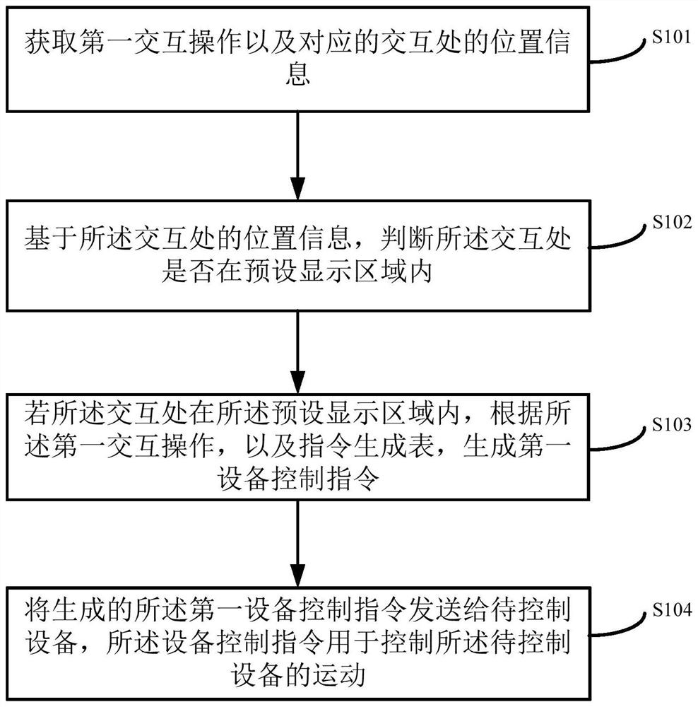
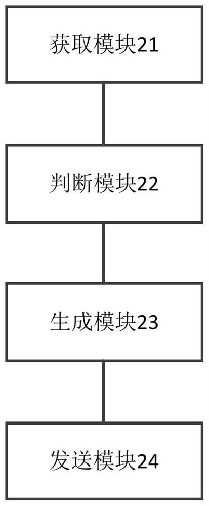
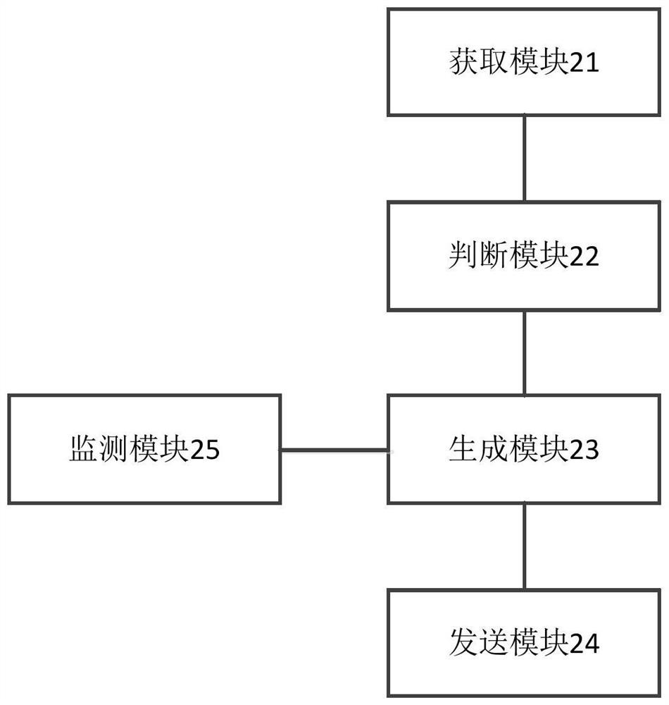
The present application provides a device control method and device, the method comprising: acquiring a first interaction operation and location information of a corresponding interaction location; based on the location information of the interaction location, judging whether the interaction location is in a preset display area If the interaction is within the preset display area, generate a first device control command according to the first interactive operation and the command generation table; the command generation table represents the preset interactive operation and device control Correspondence between instructions: sending the generated first device control instruction to the device to be controlled, where the device control instruction is used to control the movement of the device to be controlled.

Description

technical field [0001] The present application relates to the technical field of communications, and in particular, to a method, device and system for controlling an imaging device. Background technique [0002] At present, users view the video images transmitted by the image acquisition device (such as a camera) in real time through the display interface of the software client. If they want to zoom in by adjusting the focal length of the camera, they need to click a virtual button on the corresponding touch screen with the mouse, such as Zoom In / Out, corresponding to the magnification / reduction magnification respectively, to form a control command for zooming the camera, and sending the command to the control unit of the camera to control the zooming of the camera. When the corresponding virtual button is clicked, the camera starts to focus, and when the button is lifted, the camera stops focusing. However, the position of the mouse pointer at the point of interaction bet...

Claims


Application Information

Patent Timeline
Patent Type & Authority Patents(China)
IPC IPC(8): H04N5/232
CPCH04N23/66H04N23/617
Inventor 王超陈亚飞
Owner BEIJING TRICOLOR TECH
Why Eureka
Try Eureka