Coherent optical frequency transfer relay system and relay method

A relay system, coherent optical technology, applied in transmission systems, electromagnetic wave transmission systems, electrical components, etc., can solve the problems of reduced optical frequency standard signal transmission accuracy, deterioration of optical signal signal-to-noise ratio, and increased cost of relay stations. Engineering application, improving transmission accuracy, and the effect of phase noise suppression

Active Publication Date: 2021-06-01
SHANGHAI INST OF OPTICS & FINE MECHANICS CHINESE ACAD OF SCI
View PDF6 Cites 0 Cited by
  • Summary
  • Abstract
  • Description
  • Claims
  • Application Information

AI Technical Summary

Problems solved by technology

[0003] At present, optical fiber-based frequency transmission technology has made it possible to transmit and compare optical frequency standards on the order of thousands of kilometers, but this technology still has the following problems in long-distance transmission: 1. This solution needs to transmit to the far-end The optical signal returns to the local end to obtain the phase noise introduced by the optical frequency standard signal in the transmission of the optical fiber link. As the distance increases, the feedback bandwidth of the system will decrease. The feedback bandwidth will be reduced to tens of Hz, which greatly reduces the transmission accuracy of optical frequency standard signals; 2. It is necessary to place multiple bidirectional erbium-doped fiber amplifiers (EDFA) or fiber Brillouin amplifiers (FBA) in the link to Compensate for lost optical power
However, there are still two defects in this relay station structure: 1. This relay station structure only considers the amplification of the input optical signal of the previous stage, and does not amplify the optical signal transmitted by the optical fiber link of the next stage, so The single-span amplification distance is still limited. In the 1100km optical clock comparison experiment in France, three bidirectional EDFAs need to be placed between two relay stations 280km apart for auxiliary amplification, which will inevitably affect the signal-to-noise ratio of the optical signal. A certain degree of degradation; 2. When amplifying the input optical signal of the previous stage, the optical phase-locked loop scheme is adopted to lock the output phase of a high-performance narrow-linewidth laser in the system to the input optical frequency standard signal, The price of this narrow linewidth laser is usually high, adding significantly to the cost of this repeater

Method used


Image

  • Coherent optical frequency transfer relay system and relay method
  • Coherent optical frequency transfer relay system and relay method

Examples


Embodiment Construction

[0019] The present invention will be further described below in conjunction with the embodiments and accompanying drawings, but the protection scope of the present invention should not be limited thereby.

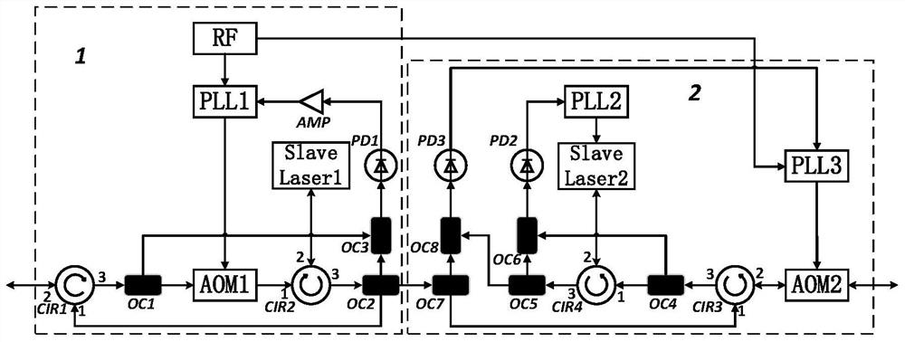
[0020] see figure 1 , figure 1 It is a schematic diagram of the structure of the coherent optical frequency transmission relay system of the present invention. It can be seen from the figure that a coherent optical frequency transmission relay system includes: a coherent receiving device 1, which is used to receive light transmitted over a long distance through an upper-level optical fiber link The frequency reference signal is used to amplify the received optical signal with low noise, and return a part of the amplified optical signal to the upper-level optical fiber link; the coherent optical receiving and noise compensation device 2 is used to output the amplified optical signal For the next-level optical fiber link, the input return optical signal is amplified with low...


PUM


Abstract

A coherent optical frequency transmission relay system and a relay method, the system uses the coherent light receiving device of the first stage to perform low-noise amplification on the optical frequency reference signal transmitted through the optical fiber link of the upper stage for a long distance, and amplifies the The optical signal is returned to the upper-level optical fiber link; the amplified optical signal is output to the next-level optical fiber link through the second-level coherent light receiving and noise compensation device, and the input return optical signal is amplified with low noise. And the phase noise introduced when the optical frequency standard signal is transmitted in the next-level optical fiber link is compensated, so that the phase of the optical frequency reference signal received at the remote end is locked to the phase of the optical frequency reference signal at the transmitting end. The technical solution of the present invention well solves the problem of the limitation of the phase-locked bandwidth of the ultra-long-distance optical frequency reference signal transmission loop and the attenuation of the signal, and greatly improves the single-span amplification distance and transmission accuracy of the optical frequency reference signal transmission.

Description

technical field [0001] The invention relates to a relay system and a relay method for optical signal transmission in an optical fiber link. In particular, it relates to a coherent optical frequency standard signal transmission relay system and a relay method. Background technique [0002] High-precision frequency standard transmission technology is of great significance in time-frequency metrology and precision measurement of basic physical quantities. The remote comparison of optical clocks requires that the transmission accuracy of the optical frequency transmission system can reach 10 on the thousand-second time scale. -18 order of magnitude, which is far beyond the performance of frequency comparisons using satellite links as the delivery medium. Therefore, high-precision optical frequency transmission technology based on optical fiber emerged as the times require. [0003] At present, optical fiber-based frequency transmission technology has made it possible to trans...

Claims


Application Information

Patent Timeline
Patent Type & Authority Patents(China)
IPC IPC(8): H04B10/293H04B10/61
CPCH04B10/293H04B10/615
Inventor 冯子桐杨飞张茜王家亮应康姜明宇陈亚晴蔡海文桂有珍
Owner SHANGHAI INST OF OPTICS & FINE MECHANICS CHINESE ACAD OF SCI
Why Eureka
Try Eureka