
A DC/DC converter topology

A topology and converter technology, applied in the direction of converting DC power input to DC power output, instruments, regulating electrical variables, etc., can solve the problem of difficult to achieve soft switching, power grid voltage and frequency, power characteristics cannot be accurately controlled, and power dispatch control effects. drop etc.

Inactive Publication Date: 2018-12-11
STATE GRID JIANGSU ELECTRIC POWER CO LTD TAIZHOU POWER SUPPLY BRANCH +1
View PDF4 Cites 4 Cited by
  • Summary
  • Abstract
  • Description
  • Claims
  • Application Information

AI Technical Summary

Problems solved by technology

But at the same time, most of these renewable energy sources cannot sustain stable output. For example, solar energy, wind energy, and tidal energy are limited by environmental factors, and their output is intermittent and uncertain, which causes these unstable electric energies to be brought to the power system during the process of inputting into the grid. to run and control instability
Affected by the randomness of the output power of renewable energy, the frequency and power characteristics of the grid voltage cannot be accurately controlled, which will easily cause the performance of the grid to decline and increase the difficulty of power system maintenance.
In order to reduce the effect of power dispatching control and other issues, various converters are required to realize the coupling conversion between different energies, and reduce the adverse impact of these power sources on the power grid while introducing the electric energy from various renewable energy and other independent power sources into the power grid
However, the existing converters have problems such as complex structure, difficulty in effectively realizing electrical isolation, difficulty in meeting high-voltage loads, and difficulty in realizing soft switching.

Method used


Image

  • A DC/DC converter topology
  • A DC/DC converter topology
  • A DC/DC converter topology

Examples


specific Embodiment approach

[0025] Its specific implementation is as follows.

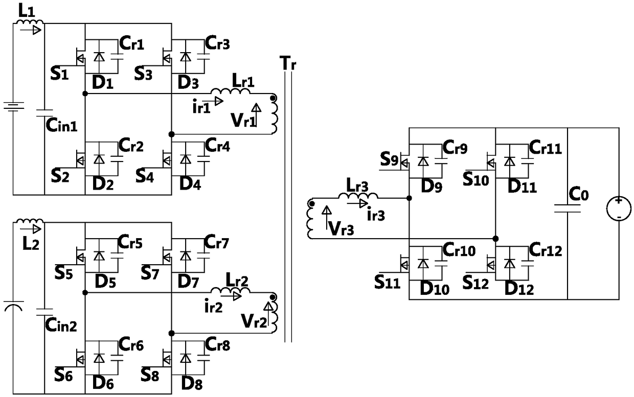
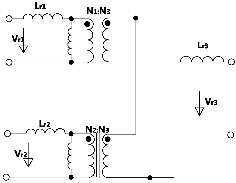
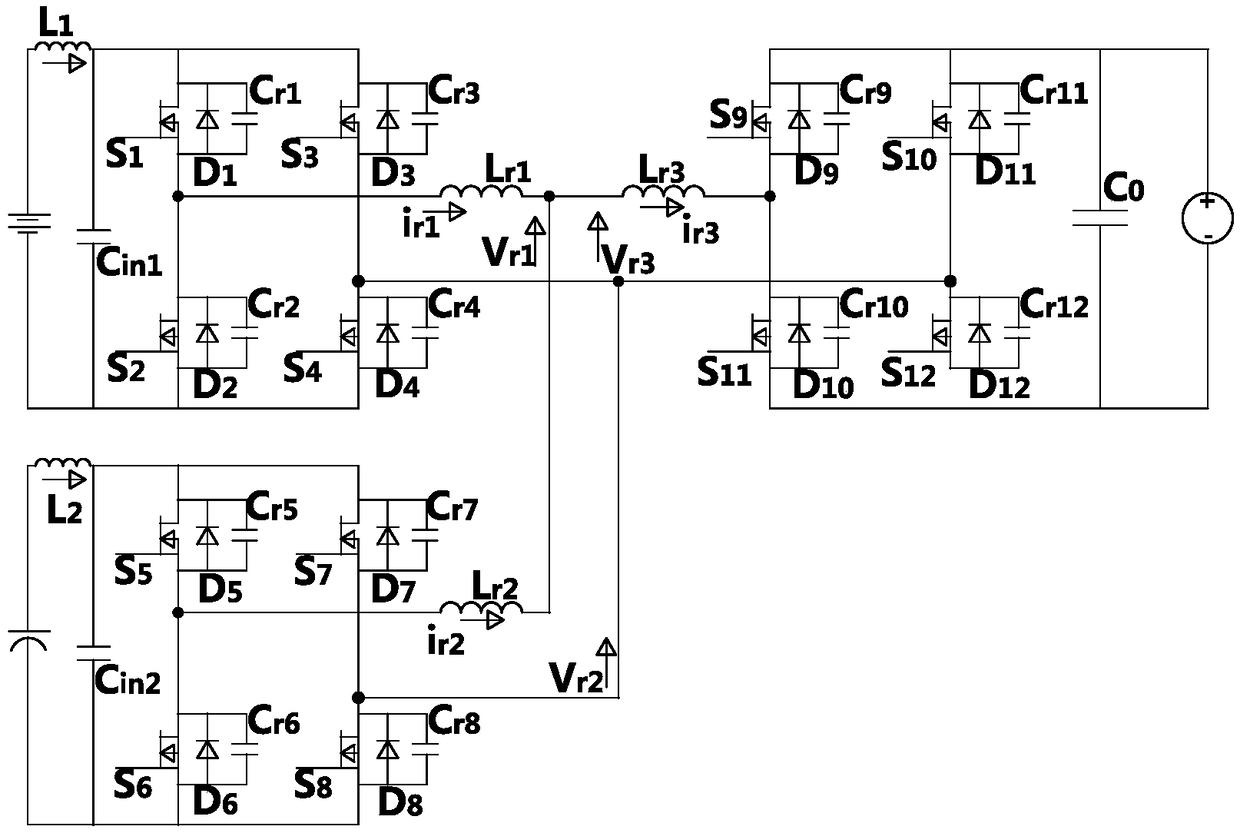
[0026] Analyze the working principle of the DC / DC converter in this scheme, in order to image 3 The original side of the equivalent circuit diagram is a reference, and the voltage and current waveforms of the DC / DC converter in one cycle are as follows Figure 4 As shown, the converter repeats the above working mode in one cycle, so it can be divided into t in one working cycle 1 -t 20 Twenty state intervals, including:

[0027] t 0 -t 1 (t 0 refers to the cycle start time point), this state is immediately following the t of the previous stable state 20 , S 1 , S 4 , S 5 , S 8 conduction, D 9 、D 12 conduction. v cr6 =v cr7 =U 2, the voltages applied to the three terminals are all positive voltages, v 2 side duty cycle less than 1, i r1 decreases linearly, i r2 and i r3 increases linearly.

[0028] t 1 -t 2 , S 5 Disconnect, C r5 、C r6 with T r resonance, C r5 Charge, C r6 discharge, v cr5 increa...


PUM


Abstract

The invention belongs to the field of power network control circuit topology, in particular to a DC / DC converter topology. According to the invention, each power source of the structure is capable oftransmitting or receiving electrical energy individually or simultaneously with a load or grid, enabling flexible two-way flow management, high frequency coupling transformer with three windings realizes electrical isolation, At that same time, the turn ratio can be designed quickly according to the voltage matching relation of the front and back terminals, Circuit and equipment design complexityis simplify, by using the shunt capacitor of the switch and the leakage inductance of the transformer to realize the resonance and energy conversion, the soft switching can be realized without the aidof the peripheral auxiliary circuit, the circuit structure is simplified, the circuit cost is reduced, the energy conversion requirement under different power can be met, and the application range ofthe converter is improved.

Description

technical field [0001] The invention belongs to the field of power grid control circuit topology, in particular to a DC / DC converter topology. Background technique [0002] With the continuous development of social economy, people's demand for electric energy is getting higher and higher. Restricted by the energy crisis and environmental problems, people have begun to vigorously develop various renewable and clean energy sources, including wind power, water power, solar energy, biomass energy, and geothermal energy. , tidal energy, etc. Among them, wind power and solar energy are rich in resources, friendly to the environment, and the resources are widely distributed. They are the two most common clean energy sources. But at the same time, most of these renewable energy sources cannot sustain stable output. For example, solar energy, wind energy, and tidal energy are limited by environmental factors, and their output is intermittent and uncertain, which causes these unstable...

Claims


Application Information

Patent Timeline
IPC IPC(8): H02M3/335
CPCH02M3/33576H02M1/0083
Inventor 梅鑫冯伟杨乐
Owner STATE GRID JIANGSU ELECTRIC POWER CO LTD TAIZHOU POWER SUPPLY BRANCH
Learn More