
Container and push mechanism thereof

A technology of pushing mechanism and container, applied in instruments, coin-operated equipment for distributing discrete items, coin-operated equipment for distributing discrete items, etc., can solve problems such as damage to goods

Pending Publication Date: 2018-12-11
北京云迹科技股份有限公司
View PDF0 Cites 2 Cited by
  • Summary
  • Abstract
  • Description
  • Claims
  • Application Information

AI Technical Summary

Problems solved by technology

[0006] The main purpose of this application is to provide a container and its pushing mechanism to solve the problem in the related art that the picking equipment can only grab the goods through the goods outlet of the vending container through the active acquisition unit such as a mechanical arm, which often causes damage to the goods. question

Method used


Image

  • Container and push mechanism thereof
  • Container and push mechanism thereof
  • Container and push mechanism thereof

Examples


Embodiment 1

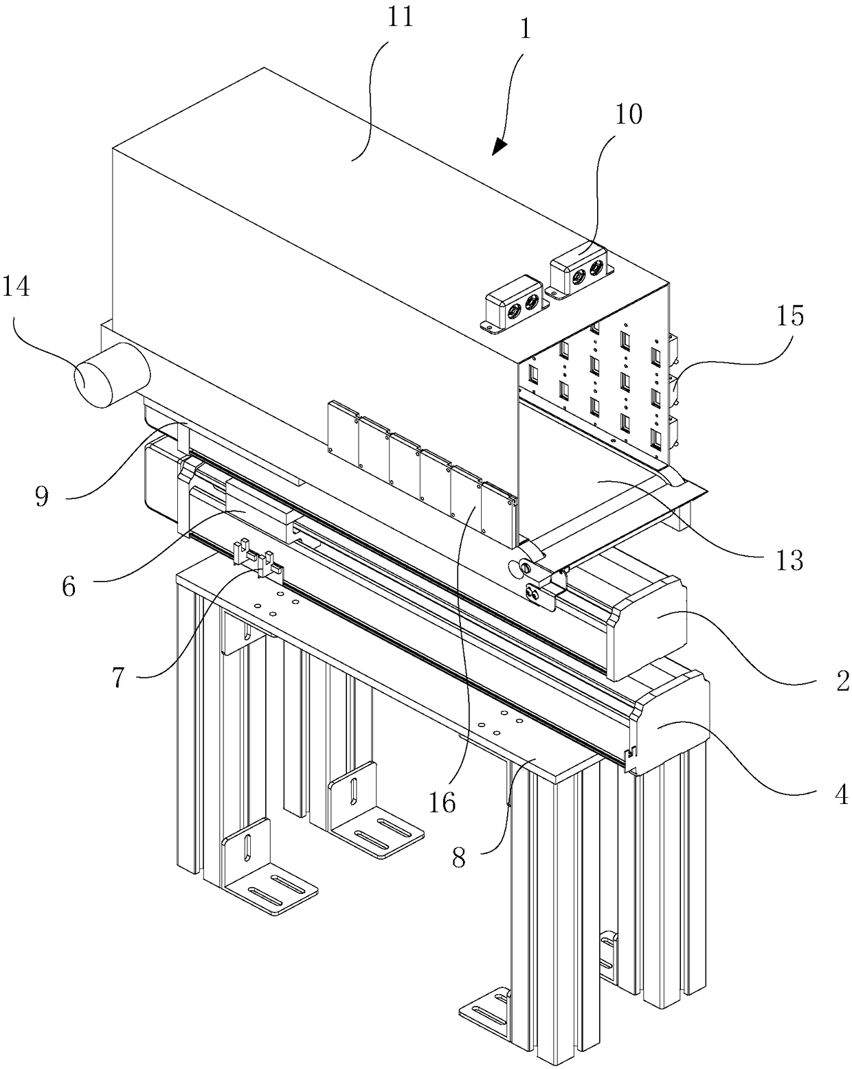
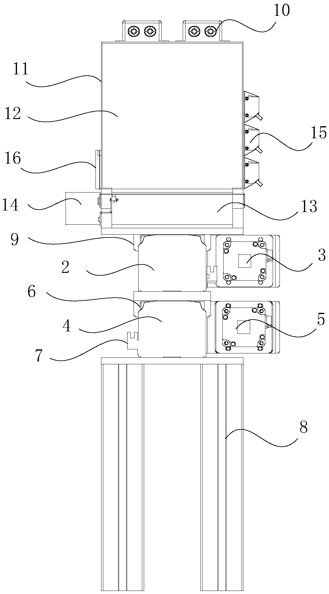
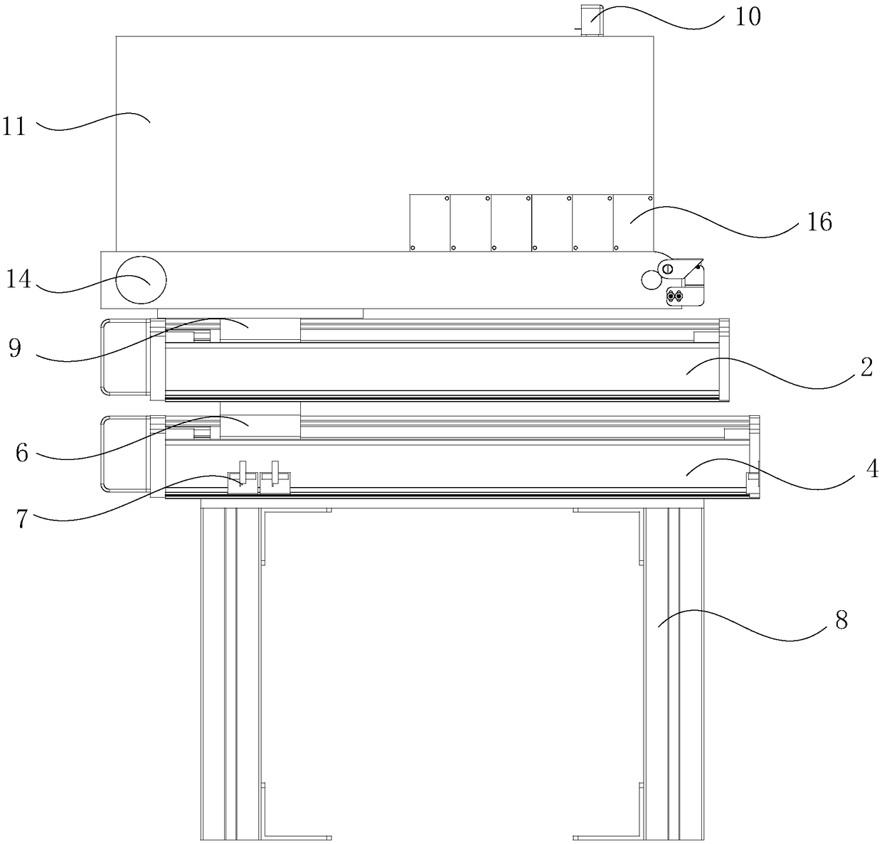
[0038] see Figure 1 to Figure 4 , the application relates to a push mechanism, comprising:

[0039] The storage mechanism 1 is used for storing goods or pushing the goods inside out of the front end of the storage mechanism 1;

[0040] The first guide rail 2, the storage mechanism 1 is connected to the first guide rail 2;

[0041] The first drive mechanism 3 is fixed on the first guide rail 2, the output end of the first drive mechanism 3 is connected with the storage mechanism 1, and the first drive mechanism 3 is used to drive the storage mechanism 1 to move on the first guide rail 2, so as to Make the front end of the storage mechanism 1 protrude from the outlet of the container and align with the receiving part of the pick-up equipment, and the storage mechanism 1 pushes the goods located inside from the front end of the storage mechanism 1 to the pick-up of the pick-up equipment department.

[0042] In the embodiment of the present application, the push mechanism uses...

Embodiment 2

[0065] An embodiment of the present application provides a container, including a housing, a delivery port, and the pushing mechanism described in Embodiment 1. The pushing mechanism is located inside the housing, and the delivery port is arranged on the housing.

[0066] In this embodiment of the application, the container adopts the push mechanism described in Embodiment 1, through which the goods can be directly pushed to the receiving part of the pick-up equipment, thereby realizing the direct push of intact goods to the pick-up equipment The technical effect of the receiving department ensures the integrity of the goods.


PUM


Abstract

The invention discloses a container and a push mechanism thereof. The push mechanism comprises a storage mechanism, a first guide rail and a first driving mechanism; the storage mechanism is used forstoring cargoes or pushing the cargoes located inside out of the front end of the storage mechanism, the storage mechanism is connected to the first guide rail, the first driving mechanism is fixed tothe first guide rail, the output end of the first driving mechanism is connected with the storage mechanism, and the first driving mechanism is used for driving the storage mechanism to move on the first guide rail, so that the front end of the storage mechanism stretches out of a cargo outlet of the container and is aligned to a cargo receiving part of cargo taking equipment; the storage mechanism pushes the cargoes located inside to the cargo receiving part of the cargo taking equipment from the front end of the storage mechanism. Accordingly, the technical problems that in the related technologies, the cargo taking equipment can stretch into the cargo outlet of the vending container to grab the cargoes only through active obtaining units such as a mechanical arm, and damage to the cargoes is caused frequently are solved.

Description

technical field [0001] The present application relates to the technical field of storage containers, in particular, to a pushing mechanism and a container. Background technique [0002] In order to facilitate people to buy things, some vending containers are placed in some hotels and other places with a large passenger flow. Some snacks, drinks, toys, charging treasures and other items are stored in the vending containers. People can buy them through these vending containers. Items stored in the vending container. [0003] In related technologies, during the process of picking up goods from the vending container, people can pick up goods manually or through picking up equipment. [0004] In the process of implementing the embodiments of the present application, the inventors found that there are at least the following technical problems in the related art: [0005] In the process of picking goods in the related art, the picking equipment can only grab the goods through the...

Claims


Application Information

Patent Timeline
Patent Type & Authority Applications(China)
IPC IPC(8): G07F11/16G07F11/26
CPCG07F11/16G07F11/26
Inventor 朱晓云耿凯哥
Owner 北京云迹科技股份有限公司
Learn More