
Multifunctional notebook computer support

A notebook computer, multi-functional technology, applied in the direction of machine/stand, supporting machine, mechanical equipment, etc., can solve the problems of inconvenient use, complex structure, high cost and other problems for users, and achieve the effect of simple structure, convenient portability and low cost

Inactive Publication Date: 2018-12-11
成都捷科菲友信息技术有限公司
View PDF0 Cites 1 Cited by
  • Summary
  • Abstract
  • Description
  • Claims
  • Application Information

AI Technical Summary

Problems solved by technology

[0003] Based on the above technical problems, the present invention provides a multifunctional notebook computer support, thereby solving the problem that the existing multifunctional notebook computer support has a complex structure and high cost when the height is changed, and the user's wrist is always in the position when the height is too high. Suspended state, resulting in inconvenient use and technical problems for users who are prone to fatigue

Method used


Image

  • Multifunctional notebook computer support
  • Multifunctional notebook computer support
  • Multifunctional notebook computer support

Examples


Embodiment 1

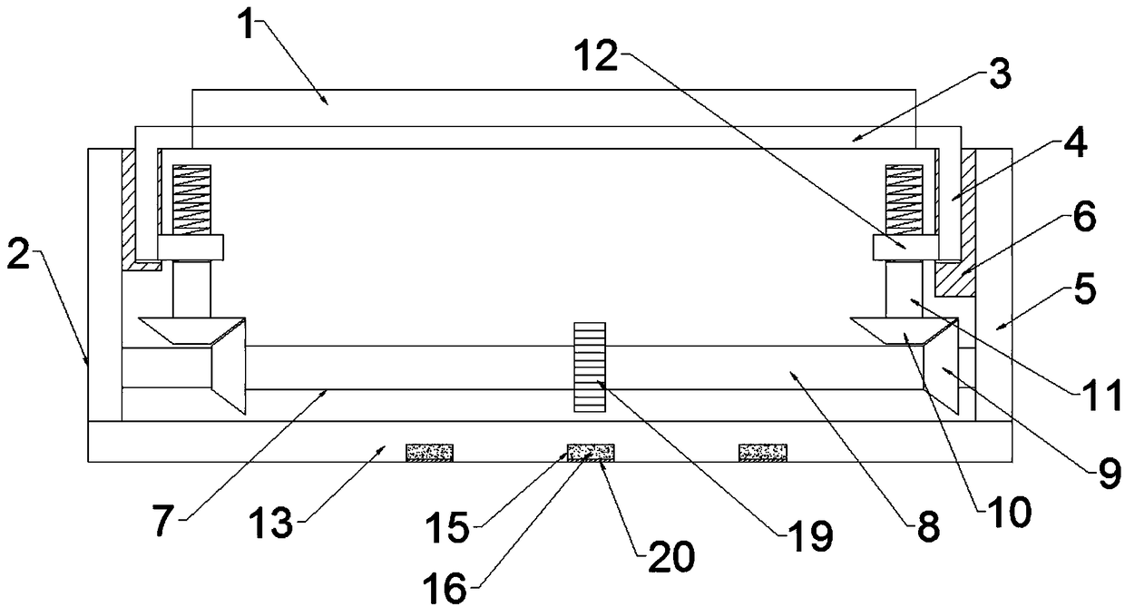
[0036] A multi-functional notebook computer support, comprising a clamping plate 1 and a base 2 arranged below the clamping plate 1; a flat plate 14 is hinged on one side of the clamping plate 1; the flat plate 14 is located on the side opposite to the clamping plate 1 A plurality of supplementary boards 21 are provided, and the flat plate 14 is provided with a first connection groove 22 at one end of the supplementary board 21, a second connection groove 23 is provided at one end of the supplementary board 21, and a second connection groove 23 is provided at one end of the supplementary board 21. The second connecting groove 23 is threadedly connected to the connecting column 24 .

Embodiment 2

[0038] This embodiment is further optimized based on Embodiment 1, and the plate 14 is connected to the clamping plate 1 through a secondary damping shaft. It is convenient to change the angle of the tablet 14 during use, so that the user can find a suitable angle to support the wrist.

Embodiment 3

[0040] This embodiment is further optimized based on Embodiment 1 or 2. The first connecting rod 3 is arranged under the clamping plate 1, the first slider 4 is arranged on the bottom of both sides of the first connecting rod 3, and the base 2 is located on the first connecting rod. The first support rod 5 is vertically arranged on both sides of the rod 3, and the first support rod 5 is located on the side of the first connecting rod 3 and is vertically provided with a first chute 6, and the first slider 4 is snapped into the first chute 6 And the first slider 4 can slide along the first chute 6;

[0041]The base 2 is located below the first slider 4 and is provided with a drive assembly 7 for driving the first slider 4 to slide. The drive assembly 7 includes a rotating shaft 8 parallel to the first connecting rod 3, and two groups of radial ends are symmetrically arranged on the rotating shaft 8. Towards the same first helical gear 9, a second helical gear 10 meshing with the...


PUM


Abstract

The invention relates to the technical field of notebook computer auxiliary devices, and discloses a multifunctional notebook computer support. The multifunctional notebook computer support comprisesa clamping plate and a base. A flat plate is hinged to one side of the clamping plate; a plurality of supplement plates are arranged on one side, opposite to the clamping plate, of the flat plate; a first connecting groove is formed in one end, located at one end of one supplement plate, of the flat plate; a second connecting groove is formed in one end of each supplement plate; connecting columnsin threaded connection with the first connecting groove and the second connecting grooves are arranged at the other ends of the supplement plates. The multifunctional notebook computer support has the advantages that a user can put the wrist on the flat plate when using a notebook computer, so that the user's wrist is prevented from fatigue due to constant suspension; when the angle of the flat plate needs to be adjusted to change the distance between the flat plate and a table top, or when the height of the base needs to be changed to change the distance between the flat plate and the tabletop, the flat plate can contact with the table top by mounting or demounting the supplement plates, so that the flat plate can be prevented from being suspended to eliminate the support effect on theuser's wrist.

Description

technical field [0001] The invention relates to the technical field of notebook computer auxiliary equipment, in particular to a multifunctional notebook computer support. Background technique [0002] Multifunctional laptop stand, the so-called lazy stand. Use in a comfortable way, according to ergonomics, the participation of man-machine design concepts, to obtain a comfortable computer experience. Different users have different requirements for the height of the multifunctional notebook computer stand, so most of the existing multifunctional notebook computer stand can adjust the height, but when the existing multifunctional notebook computer stand changes the height, the structure is complex, the cost is high, and the height is too high. When the height is high, the user's wrist is always in a suspended state, which makes the user inconvenient to use and prone to fatigue. Contents of the invention [0003] Based on the above technical problems, the present invention ...

Claims


Application Information

Patent Timeline
Patent Type & Authority Applications(China)
IPC IPC(8): F16M11/24F16M11/04
CPCF16M11/04F16M11/24
Inventor 王小斌
Owner 成都捷科菲友信息技术有限公司
Learn More