
Weighing method based on force acquisition from amplitude varying steel wire rope

A wire rope, weighing technology, applied in the direction of load hanging components, transportation and packaging, can solve the problems of inconvenient installation, hidden dangers, affecting the overall structure, etc., to achieve the effect of convenient installation and saving man-hours

Active Publication Date: 2018-12-11
YICHANG WTAU ELECTRONICS EQUIP
View PDF6 Cites 2 Cited by
  • Summary
  • Abstract
  • Description
  • Claims
  • Application Information

AI Technical Summary

Problems solved by technology

The disadvantages are also very obvious: the plate ring sensor is inconvenient to use under the requirement of assembling the arm bar, and the operation is complicated when adding or disassembling the arm bar; the shaft pin sensor needs to replace the parts of the crane, which affects the overall structure and poses a safety hazard , and the installation is inconvenient; the three-pulley sensor cannot avoid the wear of the wire rope, and there are also potential safety hazards

Method used

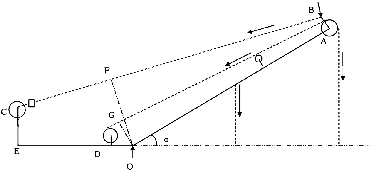
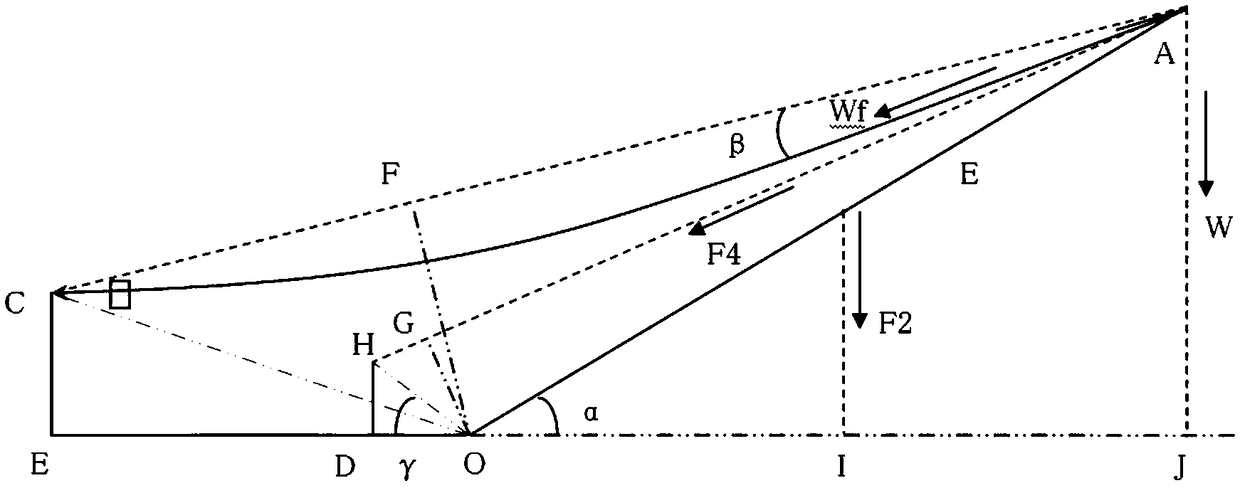

Image

  • Weighing method based on force acquisition from amplitude varying steel wire rope
  • Weighing method based on force acquisition from amplitude varying steel wire rope

Examples


Embodiment Construction

[0046] In order to make the object, technical solution and advantages of the present invention clearer, the present invention will be further described in detail below in conjunction with the accompanying drawings and embodiments. It should be understood that the specific embodiments described here are only used to explain the present invention, not to limit the present invention.

[0047] The luffing force refers to taking the tension on the luffing steel wire rope. It adopts the ordinary plate ring sensor and installs it on the fixed end of the luffing rope or on the bracket of the luffing pulley block. Refer to the attached figure 1 . According to the torque balance relationship of luffing rope tension, hoisting rope tension, boom self-weight, and load gravity, multiple parameters are determined through the operation of the commissioning site, and then the load gravity is calculated according to a set of algorithms, so as to achieve the weighing and weight of the load. Mom...


PUM


Abstract

The invention provides a weighing method based on force acquisition from an amplitude varying steel wire rope, which is characterized in that a pulling force is acquired from the amplitude varying steel wire rope, and according to a torque balance relationship among a amplitude varying rope pulling force, a lifting rope pulling force, a arm weight and a load gravity, a parameter is determined by an operation of a site commission, and then the load gravity is calculated according to a set algorithm in a torque limiter to achieve weighing and torque protection of the load.

Description

technical field [0001] The invention relates to the field of safety monitoring, in particular to a weighing method based on force taking of luffing wire ropes. Background technique [0002] Most of the existing moment limiters of lifting equipment such as crawler cranes and tire cranes use the pressure or tension generated by the load in the mechanical structure to measure the load directly, so as to achieve the purpose of moment protection for the crane. There are generally three ways to take force directly: install a ring tension sensor at the fixed end of the hoisting rope to obtain tension; replace the shaft of the fixed pulley at the top of the arm with a pin pressure sensor to obtain pressure; install three pulleys above the arm The pressure sensor takes the pressure. The direct force take-off method adopts the linear calibration method to calculate the load. The advantage is that the signal acquisition is simple and the calculation is convenient. The disadvantages a...

Claims


Application Information

Patent Timeline
IPC IPC(8): B66C13/16B66C1/12
CPCB66C1/12B66C13/16
Inventor 谢邦天高钰敏张艳波曹志勇沈毅祥李永红
Owner YICHANG WTAU ELECTRONICS EQUIP
Learn More