Clamp feeding mechanism

A feeding mechanism and clamp technology, applied in the field of automatic feeding, can solve the problems of time-consuming and laborious, damaged clamps, and inability to parallelize.

Pending Publication Date: 2018-12-11
山东艾西特数控机械有限公司
View PDF5 Cites 0 Cited by
  • Summary
  • Abstract
  • Description
  • Claims
  • Application Information

AI Technical Summary

Problems solved by technology

[0002] The common feeding mechanism currently used is a manual clamp, which needs to be manually tightened when clamping the plate, which is time-consuming and laborious, and the plate is still fixed on the clamp during processing, and the vibration generated during the process of plate processing is likely to cause the plate to

Method used


Image

  • Clamp feeding mechanism
  • Clamp feeding mechanism
  • Clamp feeding mechanism

Examples


Embodiment Construction

[0021] In order to enable those skilled in the art to better understand the technical solutions of the present invention, the present invention will be further described in detail below in conjunction with the accompanying drawings.

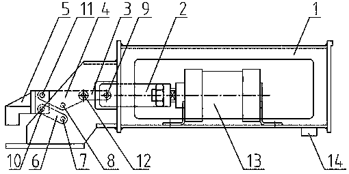
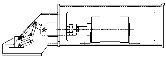
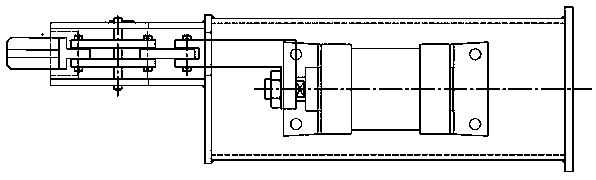
[0022] like figure 1 As shown, a clamp feeding mechanism provided by the embodiment of the present invention includes a clamp 5, a bracket 1, a transmission system, a cylinder 13 fixed on the bracket 1, and a solenoid valve 14. The solenoid valve 14 controls the extension of the output end of the cylinder 13. Out and back, the output end of the cylinder 13 is fixedly connected with the connection plate 2, the action of the cylinder 13 drives the connection plate 2 to make a reciprocating linear motion in the groove of the bracket 1, and the setting of the groove further ensures the linear motion state of the connection plate 2 .

[0023] One end of connecting rod one 3 is rotationally connected with connection plate 2 through shaft three 9, and ...


PUM


Abstract

The invention discloses a clamp feeding mechanism. According to the mechanism, a linear motion of an air cylinder can be converted into a circular motion of the clamp, the situation that a clamping plane of the clamp is parallel to the lower bottom surface of a support during a motion process is realized, surface contact is achieved when the clamp clamps a plate, the surface of the plate is not damaged, service life of the clamp feeding mechanism is guaranteed, structure is simple, action is reliable, and an electromagnetic valve controls actions of the air cylinder so as to realize automaticclamping and loosening of the clamp, time and labor are saved.

Description

technical field [0001] The invention relates to the technical field of automatic feeding, in particular to a clamp feeding mechanism. Background technique [0002] The common feeding mechanism currently used is a manual clamp, which needs to be manually tightened when clamping the plate, which is time-consuming and laborious, and the plate is still fixed on the clamp during processing, and the vibration generated during the process of plate processing is likely to cause the plate to fall off and the clamp to break. damage, affecting work efficiency. The existing clamp automatic feeding system has complex structure and time-consuming manufacture. When clamping the plate, the clamping plane of the clamp cannot be parallel to the surface of the plate during the action, which may easily cause damage to the processed plate. Contents of the invention [0003] The object of the present invention is to provide a clamp feeding mechanism, which can convert the linear motion of the...

Claims


Application Information

Patent Timeline
IPC IPC(8): B65G47/91
CPCB65G47/915
Inventor 李云稀李新焦国庆孙建磊王存义吴国龙
Owner 山东艾西特数控机械有限公司
Why Eureka
Try Eureka