Turnover bag moving and locating structure and method

A technology of mobile positioning and positioning method, applied in garbage collection, household appliances, applications, etc., can solve the problems of sanitation, hidden dangers, high labor costs, cumbersome operations, etc., and achieve the effect of convenient operation and simple structure

Active Publication Date: 2018-12-11
成都智叟智能科技有限公司
View PDF5 Cites 1 Cited by
  • Summary
  • Abstract
  • Description
  • Claims
  • Application Information

AI Technical Summary

Problems solved by technology

[0004] The technical problem to be solved by the present invention is: in the existing garbage recycling process, the garbage is directly put into the garbage bin, and the harmful garbage in the garbage bin is removed by the staff later, the operation is cumbersome, the labor cost is high, and in the process Unavoidable contact with garbage, there are certain health and safety hazards, the present invention provides a turnover bag mobile positioning structure and method to solve the above problems

Method used


Image

  • Turnover bag moving and locating structure and method
  • Turnover bag moving and locating structure and method
  • Turnover bag moving and locating structure and method

Examples


Embodiment 1

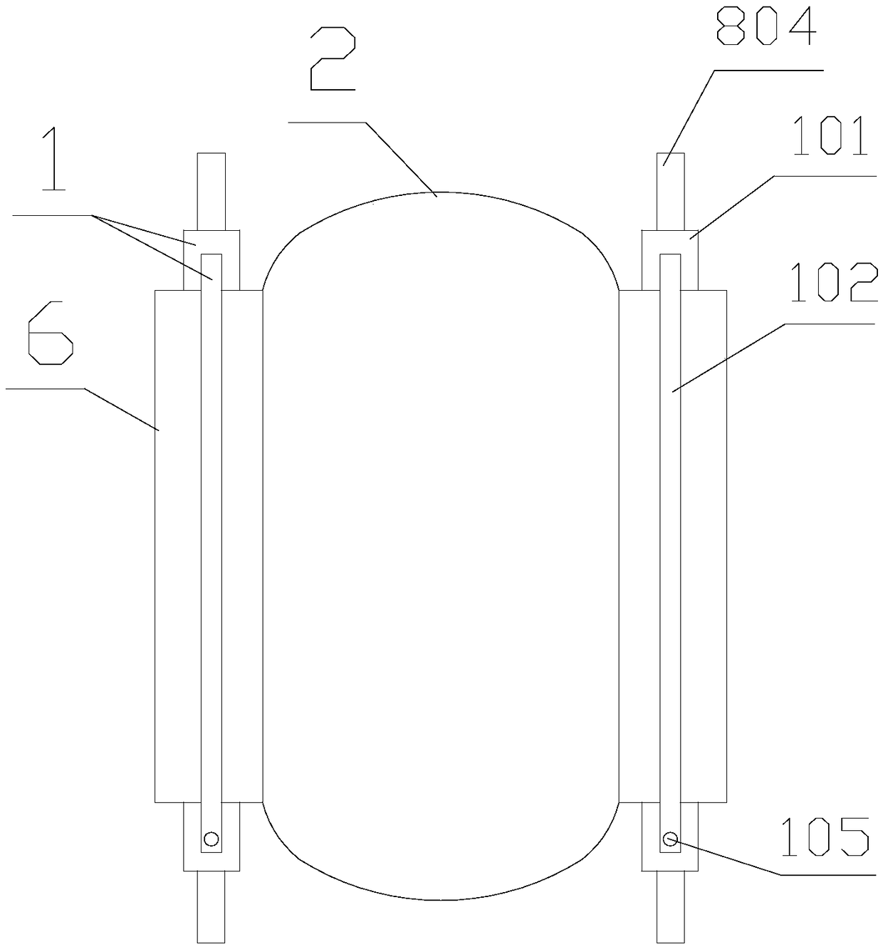
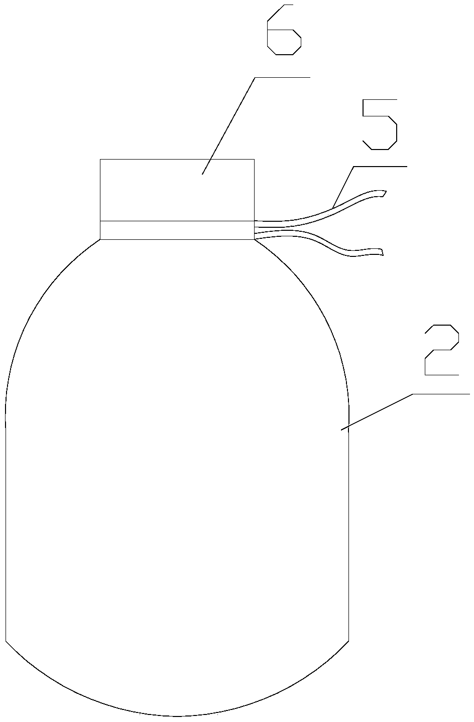
[0044] The invention provides a mobile positioning structure for a turnover bag, which includes a positioning splint 1, a guide mechanism 8 and a control terminal; There are several virtual positions 4, the positioning splint 1 is erected at the mouth of the corresponding virtual position 4 on the storage bin 3, the turnover bag 2 is accommodated in the virtual position 4, the axis direction of the positioning splint 1 is perpendicular to the axis direction of the storage bin 3, The axial length of positioning splint 1 is greater than the radial length of storage bin 3; Described guiding mechanism 8 comprises linear guide rail 801 and slide block 802, and linear guide rail 801 is located at the warehouse mouth place of storage bin 3, and the axial direction and storage bin 3 The axial directions of the two slides are parallel, and the slide block 802 slides along the linear guide rail 801; two slide blocks 802 are symmetrically arranged on both sides of the mouth of each virtua...

Embodiment 2

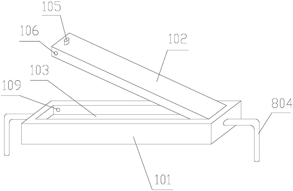
[0046] Further improvement on the basis of Embodiment 1, the positioning splint 1 includes a fixing plate 101 and a pressing plate 102, the upper surface of the fixing plate 101 is provided with a fixing groove 103 embedded in the holding pressing plate 102; the pressing plate 102 One end of the axial direction is connected to the inner wall of one end of the fixing groove 103 through a pin shaft, and the axial direction of the pin shaft is perpendicular to the axial direction of the pressure plate 102; the other axial end of the pressure plate 102 is detachably connected to the other axial end of the fixing groove 103; The pocket edge of the turnover bag 2 is pressed between the fixing groove 103 and the pressing plate 102.

Embodiment 3

[0048] Further improvement on the basis of Embodiment 2, the pressure plate 102 is provided with a mounting hole 104 on the surface away from the rotating connection end plate, and also includes an adjustment column 105, one axial end of the adjustment column 105 is inserted into the installation hole 104, and the other end is The protruding pressure plate 102 is set on the plate surface; the two sides of the pressure plate 102 are symmetrically provided with fixing holes 106, the fixing holes 106 communicate with the installation hole 104, and the axis direction of the fixing hole 106 is perpendicular to the axis direction of the installation hole 104; The fixing hole 106 is provided with a limit post 107, the limit post 107 is covered with a return spring 108, and the fixing hole 106 and the limit post 107 are provided with an adapted spring stopper, the spring stopper includes a stop ring plate 111 and positioning sleeve 112, the limit ring plate 111 is sleeved on the limit ...


PUM


Abstract

The invention discloses a turnover bag moving and locating structure and method. The turnover bag moving and locating structure comprises locating clamping plates, guiding mechanisms and a control terminal; the two sides of the edges of a bag opening of a turnover bag are detachably fixed to the locating clamping plates respectively; a storage bin is provided with several virtual bin spaces in theaxial direction, and the locating clamping plates are erected at the portion, on bin ports of the corresponding virtual bin spaces, on the storage bin; the guiding mechanisms are arranged at the binports of the storage bin, and the two axial ends of each locating clamping plate are connected with the corresponding guiding mechanism and follow the guiding mechanism to slide in the axial directionof the storage bin; electronic plug locks are arranged in slide blocks, indicator lamps are further arranged on the outer side walls of the slide blocks, and the control terminal is electrically connected with the electronic plug locks and the indicator lamps. The locating method comprises the following steps of numbering and storing all the virtual bin spaces and the corresponding slide blocks in the storage bin, and selecting started virtual bin spaces; utilizing the control terminal for controlling the electronic plug locks on the corresponding slide blocks. According to the turnover bag moving and locating structure, garbage recycling is facilitated, accurate locating of the turnover bag is achieved, and garbage is accurately put.

Description

technical field [0001] The invention relates to the field of environmental protection technology, in particular to a structure and method for moving and positioning turnover bags. Background technique [0002] Garbage refers to unnecessary or useless solid and fluid substances. In densely populated cities, garbage disposal is a headache. The common way is to collect it and send it to landfill or incinerate it with an incinerator. Both of them will create environmental protection problems, and ending excessive consumption can further reduce the saturation of landfills. Improper disposal of garbage in landfills will pollute groundwater and emit bad smells, and the area available for landfills in many cities has become less and less. The less, incineration will inevitably produce toxic gases and harm organisms. Most cities are researching ways to reduce waste generation and encourage resource recycling. [0003] In the existing garbage recycling process, garbage, such as metal...

Claims


Application Information

Patent Timeline
Patent Type & Authority Applications(China)
IPC IPC(8): B65F1/14
CPCB65F1/1415B65F2210/112
Inventor 王俊杰
Owner 成都智叟智能科技有限公司
Why Eureka
Try Eureka