Injection mold

A technology of injection mold and end face, which is applied in metal processing and other directions, can solve the problems of affecting processing efficiency, difficulty, and non-adjustable rotation orientation, etc., and achieve the effect of reducing operation steps, improving processing efficiency and simple structure

Inactive Publication Date: 2018-12-11
奉化拓升商贸有限公司
View PDF0 Cites 0 Cited by
  • Summary
  • Abstract
  • Description
  • Claims
  • Application Information

AI Technical Summary

Problems solved by technology

[0002] Cylindrical injection molds are widely used in modern industrial production, but these cylindrical injection molds need to be drilled in the circumferential direction during production, and the rotation orientation of the traditional mold processing device cannot be adjusted after the mold is fixed. It is difficult to punch holes in the circumferential direction of the mold, which seriously affects the processing efficiency

Method used


Image

  • Injection mold
  • Injection mold
  • Injection mold

Examples


Embodiment Construction

[0025] All features disclosed in this specification, or steps in all methods or processes disclosed, may be combined in any manner, except for mutually exclusive features and / or steps.

[0026] Any feature disclosed in this specification (including any appended claims, abstract and drawings), unless expressly stated otherwise, may be replaced by alternative features which are equivalent or serve a similar purpose. That is, unless expressly stated otherwise, each feature is one example only of a series of equivalent or similar features.

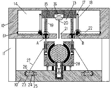
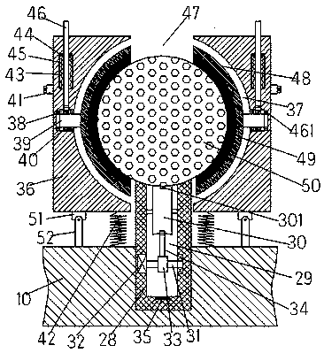
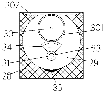
[0027] like Figure 1-5As shown, an injection mold of the device of the present invention includes a frame 10 and a top frame 12 fixedly arranged above the frame 10 through a vertical rod 11, and the top end surface of the frame 10 is provided with an opening facing upward. The installation groove is fixed with an upwardly extending installation column 28, and the top end surface of the installation column 28 is provided with a concave cavity...


PUM


Abstract

The invention discloses an injection mold which comprises a frame base and a top frame fixedly arranged above the frame base through a vertical bar. The top end surface of the frame base is internallyprovided with a mounting groove with the upward opening end, and an upwards-extending mounting column is fixedly arranged in the mounting groove, and the top end surface of the mounting column is internally provided with a cavity with the upward opening end. A mold is rotatably mounted in the cavity, the inner bottom wall of the cavity is provided with a first rotating cabin in a downward extending mode, and the first rotating cabin is rotatably provided with a first rotating rod. The right side end of the rotating rod is rotatably arranged in the inner wall of the right side of the first rotating cabin, and the left side end of the rotating rod is in power connection with a first motor fixedly arranged in the inner wall of the left side of the first rotating cabin. A rotating round wheelis fixedly arranged on the first rotating rod, and a fan-shaped conductive tooth is fixedly arranged on the outer circle of the rotating round wheel.

Description

technical field [0001] The invention relates to the technical field of mold processing, in particular to an injection mold. Background technique [0002] Cylindrical injection molds are widely used in modern industrial production, but these cylindrical injection molds need to be drilled in the circumferential direction during production, and the rotation orientation of the traditional mold processing device cannot be adjusted after the mold is fixed. It is very difficult to punch holes in the circumferential direction of the mold, which seriously affects the processing efficiency. Contents of the invention [0003] Aiming at the deficiencies of the above-mentioned technologies, the present invention proposes an injection mold. [0004] An injection mold of the device of the present invention comprises a stand and a top frame fixed above the stand by a vertical rod, and an installation groove with an upward opening is arranged in the top end surface of the stand, and in ...

Claims


Application Information

Patent Timeline
Patent Type & Authority Applications(China)
IPC IPC(8): B26F1/16B26D5/06B26D5/08B26D7/02B26D7/06
CPCB26F1/16B26D5/06B26D5/083B26D7/02B26D7/06
Inventor 毛杰
Owner 奉化拓升商贸有限公司
Why Eureka
Try Eureka