Back pounding device for low back pain
A kind of equipment and back technology, which is applied in the field of back beating equipment, can solve the problems of patients being too busy manually and inconvenient for patients to beating for a long time
- Summary
- Abstract
- Description
- Claims
- Application Information
AI Technical Summary
Problems solved by technology
Method used
Image
Examples
Embodiment 1
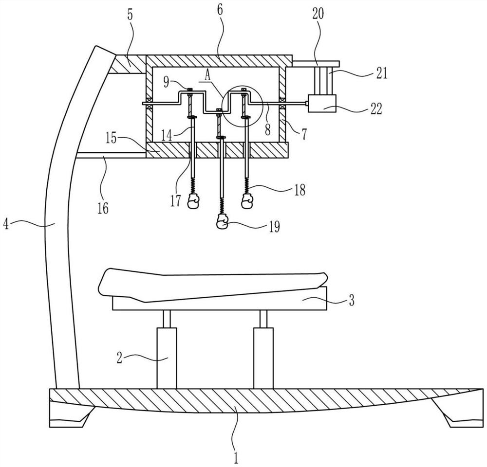
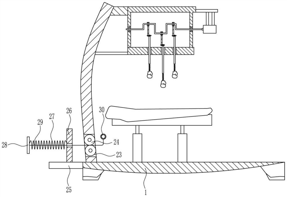
[0027] A back pounding device for low back pain, such as Figure 1-7 As shown, it includes base plate 1, first cylinder 2, bed plate 3, first bracket 4, first fixed plate 5, n-shaped frame 6, first bearing seat 7, crankshaft 8, sliding sleeve 9, connecting plate 10, guide Bar 12, turn roller 13, connecting rod 14, cross plate 15, support plate 16, the first spring 18, beat piece 19, the first installation plate 20, installation bar 21 and motor 22, the left side on the base plate 1 is installed with two A first cylinder 2, a bed board 3 is connected between the tops of the telescopic rods of the two first cylinders 2, a first bracket 4 is connected to the bottom plate 1 on the left side of the first cylinder 2 on the left side, and a first bracket 4 is connected to the right side of the first bracket 4. The upper part is connected with the first fixed plate 5, and the right side of the first fixed plate 5 is connected with the n-shaped frame 6, and the middle part of the left ...
Embodiment 2
[0029] A back pounding device for low back pain, such as Figure 1-7 As shown, it includes base plate 1, first cylinder 2, bed plate 3, first bracket 4, first fixed plate 5, n-shaped frame 6, first bearing seat 7, crankshaft 8, sliding sleeve 9, connecting plate 10, guide Bar 12, turn roller 13, connecting rod 14, cross plate 15, support plate 16, the first spring 18, beat piece 19, the first installation plate 20, installation bar 21 and motor 22, the left side on the base plate 1 is installed with two A first cylinder 2, a bed board 3 is connected between the tops of the telescopic rods of the two first cylinders 2, a first bracket 4 is connected to the bottom plate 1 on the left side of the first cylinder 2 on the left side, and a first bracket 4 is connected to the right side of the first bracket 4. The upper part is connected with the first fixed plate 5, and the right side of the first fixed plate 5 is connected with the n-shaped frame 6, and the middle part of the left ...
Embodiment 3
[0032] A back pounding device for low back pain, such as Figure 1-7 As shown, it includes base plate 1, first cylinder 2, bed plate 3, first bracket 4, first fixed plate 5, n-shaped frame 6, first bearing seat 7, crankshaft 8, sliding sleeve 9, connecting plate 10, guide Bar 12, turn roller 13, connecting rod 14, cross plate 15, support plate 16, the first spring 18, beat piece 19, the first installation plate 20, installation bar 21 and motor 22, the left side on the base plate 1 is installed with two A first cylinder 2, a bed board 3 is connected between the tops of the telescopic rods of the two first cylinders 2, a first bracket 4 is connected to the bottom plate 1 on the left side of the first cylinder 2 on the left side, and a first bracket 4 is connected to the right side of the first bracket 4. The upper part is connected with the first fixed plate 5, and the right side of the first fixed plate 5 is connected with the n-shaped frame 6, and the middle part of the left ...
PUM
 Abstract
Description
Claims
Application Information
 - Generate Ideas
- Intellectual Property
- Life Sciences
- Materials
- Tech Scout
- Unparalleled Data Quality
- Higher Quality Content
- 60% Fewer Hallucinations
Browse by: Latest US Patents, China's latest patents, Technical Efficacy Thesaurus, Application Domain, Technology Topic, Popular Technical Reports.
© 2025 PatSnap. All rights reserved.Legal|Privacy policy|Modern Slavery Act Transparency Statement|Sitemap|About US| Contact US: help@patsnap.com


